Hydraulics and heat

   / Hydraulics and heat #31  
JD CC system with high pressure internal leak or when OC valve is installed can generate a lot of heat.
 
   / Hydraulics and heat #32  
Shootin from the hip, here:

I read back looking for details, and in post #20 the OP said his saw worked on the JCB as set up for OC. If JCB is thus, then I go back to the U/S 1/4" Tee esp w/out knowing where it's situated in any continuous flow path.

A possible restriction in the 'main' still seems troublesome (GPM cap ~50% of 3/8" fittings & existing lines). Are we trying to shove a steady (OC) ~8 gpm thru ~4 gpm bits, and generating heat and pressure by doing so? (IMO the flow divider is rendered ineffective if downstream of the tee, should have been helpful otherwise...)

Any 1/4" plumbing on the Farmall? Tee/gauge added for the peeler?
 
   / Hydraulics and heat #33  
The flow divider is doing absolutely nothing to reduce your total flow as plumbed. 8gal/min comes out through 1 hose, 8gal/min returns through 1 hose. If the bypassed fluid was returned to tank via a separate hose, it might help some. As was stated above, you need to be sure that the tractor & machine are both either OC or CC systems. It will not work properly with mixed systems.
 
   / Hydraulics and heat #34  
I cant add anything useful to this discussion except to comment on Tomnoh post. My first thoughts where also that the divider valve might not be plumbed correctly so I looked it up here, Webtec - Hydraulics - Downloads - Literature and it appears to be installed correctly. going off the numbers posted for the valve,2FV2V-, it appears it doesnot have a internal relief, but the next valve, RV2FV2V does have a relief. I can only guess the accuratecy of the numbers posted, but in the event the DV in question is in fact a RV2FV2V with internal relief, it could be possible that that relief is set to high and might need some adjustment. Also in the pdf file of the hydraulic circuit, that design doesnt make sense. No relief between pump and control valves, suggesting maybe a closed center system, but all control valves are open center, a relief valve on the return stroke of the last cyl circuit and the installation of a check valve on the return side after the relief. I dont understand the reasoning. I do realize tho that this is not the actual schematic of the machine in question.
 
   / Hydraulics and heat #35  
I cant add anything useful to this discussion except to comment on Tomnoh post. My first thoughts where also that the divider valve might not be plumbed correctly so I looked it up here, Webtec - Hydraulics - Downloads - Literature and it appears to be installed correctly. going off the numbers posted for the valve,2FV2V-, it appears it doesnot have a internal relief, but the next valve, RV2FV2V does have a relief. I can only guess the accuratecy of the numbers posted, but in the event the DV in question is in fact a RV2FV2V with internal relief, it could be possible that that relief is set to high and might need some adjustment. Also in the pdf file of the hydraulic circuit, that design doesnt make sense. No relief between pump and control valves, suggesting maybe a closed center system, but all control valves are open center, a relief valve on the return stroke of the last cyl circuit and the installation of a check valve on the return side after the relief. I dont understand the reasoning. I do realize tho that this is not the actual schematic of the machine in question.


I agree, priority flow divider is plumbed as designed, but it is a PRIORITY flow divider valve, meant for another use, not for the intended use in this application. It is meant to assure hydraulic flow to circuit #1 regardless of what circuit #2 does. Circuit #2 gets the portion of flow that circuit #1 does not use. If that is ZERO, then circuit #2 gets ZERO flow. It does NOT just divide flow 50/50.
 
   / Hydraulics and heat
  • Thread Starter
#36  
Thanks for the replies. I've been doing some research and a fella on heavy equipment forum was kind enough to give me the hydraulic system information.

jcb212shyd.jpg
 
   / Hydraulics and heat
  • Thread Starter
#37  
I cant add anything useful to this discussion except to comment on Tomnoh post. My first thoughts where also that the divider valve might not be plumbed correctly so I looked it up here, Webtec - Hydraulics - Downloads - Literature and it appears to be installed correctly. going off the numbers posted for the valve,2FV2V-, it appears it doesnot have a internal relief, but the next valve, RV2FV2V does have a relief. I can only guess the accuratecy of the numbers posted, but in the event the DV in question is in fact a RV2FV2V with internal relief, it could be possible that that relief is set to high and might need some adjustment. Also in the pdf file of the hydraulic circuit, that design doesnt make sense. No relief between pump and control valves, suggesting maybe a closed center system, but all control valves are open center, a relief valve on the return stroke of the last cyl circuit and the installation of a check valve on the return side after the relief. I dont understand the reasoning. I do realize tho that this is not the actual schematic of the machine in question.

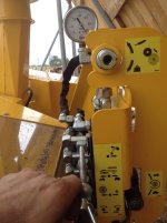
I believe there is a relief valve in the first circuit as the drive wheels can jam and the tractor does not big down as if a huge load is being applied. There is a dial toad just the wheel speed/flow so I assume it is built into that. Bottom right hand corner in the pic.
IMG_0147.jpgIMG_0147.jpg

The relief valve on the top circuit is designed to make the pressure on the arm adjustable depending on the material being processed.

I believe the check valve is to prevent issues if the hydraulic flow on the tractor was accidentally switched. That was the first thing they had me remove when troubleshooting but it made no difference.
 
   / Hydraulics and heat
  • Thread Starter
#38  
I agree, priority flow divider is plumbed as designed, but it is a PRIORITY flow divider valve, meant for another use, not for the intended use in this application. It is meant to assure hydraulic flow to circuit #1 regardless of what circuit #2 does. Circuit #2 gets the portion of flow that circuit #1 does not use. If that is ZERO, then circuit #2 gets ZERO flow. It does NOT just divide flow 50/50.

This makes sense. They had it adjusted to the max setting and I turned it down to just over half way but it did not make a difference in temp or machines performance.
 
   / Hydraulics and heat
  • Thread Starter
#39  
The flow divider is doing absolutely nothing to reduce your total flow as plumbed. 8gal/min comes out through 1 hose, 8gal/min returns through 1 hose. If the bypassed fluid was returned to tank via a separate hose, it might help some. As was stated above, you need to be sure that the tractor & machine are both either OC or CC systems. It will not work properly with mixed systems.

I agree. all goes through 1 hose in and 1 hose out. Tractor and machine are open circuit. Tractor is rated for 19 gpm and the machine requires 8 gpm.
 
 
Top