Razzmatazz
Member
My wife and son gifted me with a Yanmar SA425. The tractor is awesome but I wanted a few additions.
First up was a hydraulic top link. The SA425 includes rear hydraulics so this was a easy install.
Secondly was a grapple and third function. This was financed by the sale of my YM1700B.
Next my grandson pointed out this tractor didn't have a horn. And I had already noticed a lack of work lights.
I then caught myself driving down the paved driveway (more than once) in four wheel drive.
From the electrical standpoint, my planned improvements would overwhelm the 10 amp OEM auxiliary circuit under the seat. So I planned on including relay(s), to manage the current draw.
I was lucky enough to have the help of my brother for this project. Some of what we did might be overkill, but better safe than sorry. All the wiring is wrapped in wire loom.
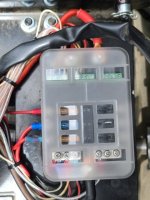
First we mounted a relay controlled fuse block under the seat. We ran 8-gauge cable from the battery to the fuse block. The OEM auxiliary circuit is controlled by the ignition switch, so this triggers the fuse block.
The horn is mounted beneath the factory grill gaurd. The switch is mounted in the factory cut-out in the fender below the PTO selector. The horn is powered through the fuse block with a 5-amp fuse.
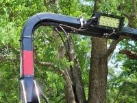
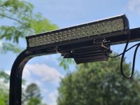
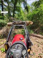
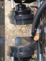
The light bars are mounted to the ROPS with stainless steel u-bolts. The lights are wired to the fuse block with 12-gauge wire. The switches are mounted in the switch box.
The switch box is mounted above the storage cubby and is behind the FEL joystick. The USB Charger/voltmeter is also mounted in the switch box.
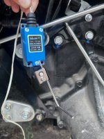
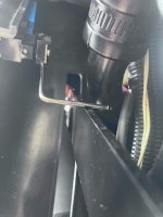
The most challenging part of the project, was the FWD indicator. The LED is mounted in the dash above the headlight control. The arm of the limit switch is bent at a 90 degree angle. The switch is wired in a normally closed configuration. The switch is mounted so that the arm is displaced against the FWD control lever. When the control lever is moved down to the FWD position, the arm descends to the closed position powering on the LED. The LED is very visible even in the south Alabama sunshine.
https://a.co/d/5iEJzlY Horn
https://a.co/d/9KTKDqs Fuse Block
https://a.co/d/8IgEQlJ Switch Box
https://a.co/d/7TbzTg7 Light Switches
https://a.co/d/4GVNvdE Horn Switch
https://a.co/d/1r7iUxW USB Charger
https://a.co/d/gjpPUb6 Green LED
https://a.co/d/gjpPUb6 Lever Arm Momentary Contact Limit Switch
https://a.co/d/fDR2Z28 7-inch Light Bar
https://a.co/d/2jo2h2C 20-inch Light Bar
First up was a hydraulic top link. The SA425 includes rear hydraulics so this was a easy install.
Secondly was a grapple and third function. This was financed by the sale of my YM1700B.
Next my grandson pointed out this tractor didn't have a horn. And I had already noticed a lack of work lights.
I then caught myself driving down the paved driveway (more than once) in four wheel drive.
From the electrical standpoint, my planned improvements would overwhelm the 10 amp OEM auxiliary circuit under the seat. So I planned on including relay(s), to manage the current draw.
I was lucky enough to have the help of my brother for this project. Some of what we did might be overkill, but better safe than sorry. All the wiring is wrapped in wire loom.
First we mounted a relay controlled fuse block under the seat. We ran 8-gauge cable from the battery to the fuse block. The OEM auxiliary circuit is controlled by the ignition switch, so this triggers the fuse block.
The horn is mounted beneath the factory grill gaurd. The switch is mounted in the factory cut-out in the fender below the PTO selector. The horn is powered through the fuse block with a 5-amp fuse.
The light bars are mounted to the ROPS with stainless steel u-bolts. The lights are wired to the fuse block with 12-gauge wire. The switches are mounted in the switch box.
The switch box is mounted above the storage cubby and is behind the FEL joystick. The USB Charger/voltmeter is also mounted in the switch box.
The most challenging part of the project, was the FWD indicator. The LED is mounted in the dash above the headlight control. The arm of the limit switch is bent at a 90 degree angle. The switch is wired in a normally closed configuration. The switch is mounted so that the arm is displaced against the FWD control lever. When the control lever is moved down to the FWD position, the arm descends to the closed position powering on the LED. The LED is very visible even in the south Alabama sunshine.
https://a.co/d/5iEJzlY Horn
https://a.co/d/9KTKDqs Fuse Block
https://a.co/d/8IgEQlJ Switch Box
https://a.co/d/7TbzTg7 Light Switches
https://a.co/d/4GVNvdE Horn Switch
https://a.co/d/1r7iUxW USB Charger
https://a.co/d/gjpPUb6 Green LED
https://a.co/d/gjpPUb6 Lever Arm Momentary Contact Limit Switch
https://a.co/d/fDR2Z28 7-inch Light Bar
https://a.co/d/2jo2h2C 20-inch Light Bar
Attachments
-
 Back_Light.jpg293.3 KB · Views: 81
 -
 Front_Light.jpg121.8 KB · Views: 78
 -
 Fuse_Block (Custom).jpg167.1 KB · Views: 83
 -
 FWD_Indicator (Custom).jpg364.8 KB · Views: 82
 -
 FWD_Switch1 (Custom).jpg158.6 KB · Views: 78
 -
 FWD_Switch2 (Custom).jpg71.7 KB · Views: 74
 -
 Horn_Switch (Custom).jpg99.3 KB · Views: 80
 -
 Horns (Custom).jpg149.3 KB · Views: 133
