OP
boggen
Elite Member
- Joined
- Feb 22, 2011
- Messages
- 3,829
- Location
- Trivoli, IL
- Tractor
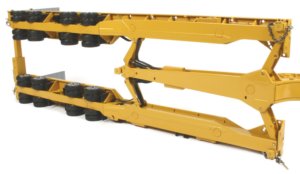
- SSTT (Sideways Snake Tain Tractor) and STB (sideways train box) tractor, dirt harvester
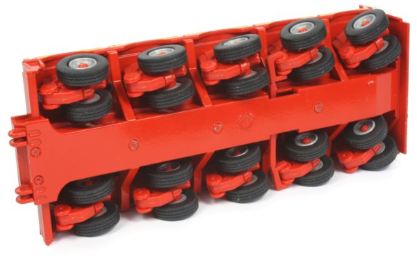
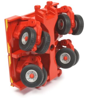
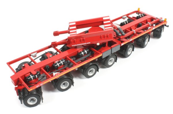
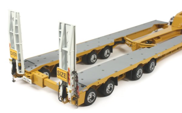
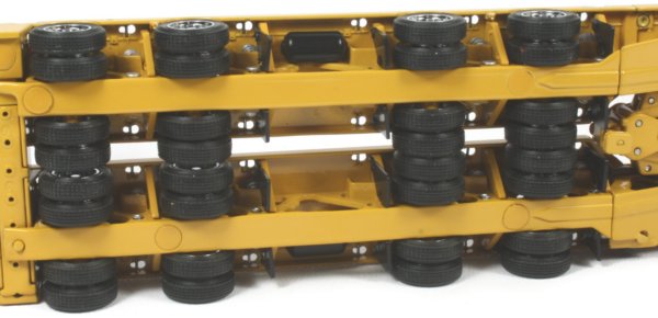
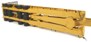
transport wheels.... eletrical wheel hub motor, brakes, suspension, and rotation of wheel in one small package.
https://www.youtube.com/watch?v=8tLQ2-yKT4Y
to above video, redoing suspension, a little bit to raise and lower wheels possibly.
also to above video, tire pressure gauge... never thought about a wireless sensor. that has some sort of "motion" generator in it. to produce electricity. (as the generator / sensor rotates around the wheel, the rotation itself causes generator to spin)
ok, finally hit me, seeing the video, it finally hit me. hyd motor vs electrical motors. and that is the internal parts. or rather. a hyd motor, is going to require some sort of cylinders and rods to create the rotation force. vs a eletrical motor. only has 1 single rotational part.
i take above back geared typed of hyd motors / hyd pumps. less moving parts = less wear and tear long term. but in order to get to something advanced enough in hyd motors to adjust RPM's and/or Torque there would be a need for a good amount of additional mechanical parts that move...
================
hit wikipedia, for electrical motors, and found my way onto, relays, and never even thought about use of them. and used like a pressurize relief valve in hydraulics. so much amps / volts and a relay begins opening or closing the circuit some, to change amount of amps / volts going to the motor.
================
do not have a slightest idea about math / formulas / equations, to even to begin to roughly size a motor based, on wire gauge, and loops in a winding/coil. to produce either RPM's and/or torque.
the other part is.... multi phase wiring.... and can i get past the DC to A/C conversion at the generator. awe..... wire gauge and distance being ran...
================
other issue, is water jacket, if electrical motor needs cooling. and then emergency brake / fail safe brake. and then some sort of cover for the brakes themselves.


 I'm very impressed with your efforts! Keep up the good work! :thumbsup: