open hydraulics

   / open hydraulics #31  
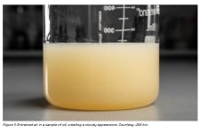
Or you can diagnose a suction air leak by taking a fluid sample from the sump or return line. Once it has warmed up, a suction leak turns the normally clear hydraulic fluid into a cloudy mix due to all the micro bubbles. Let it stand overnight without a lid and the fluid will clear up.
rscotty
 

Attachments

  • Screenshot 2025-07-31 at 8.56.36 AM.jpg
    Screenshot 2025-07-31 at 8.56.36 AM.jpg
    518.9 KB · Views: 5
   / open hydraulics #32  
The good and nice to use flow raters for hydraulic testing are expensive roughly $3000 and up. A suitable substitute can be built for a more reasonable cost.
Start out with a high pressure gauge;
1754054939146.png


An adjustable flow control valve;
1754054858077.png


then an inexpensive flow meter;
1754055293849.png


Assemble with the flow meter being the last component in the system, with no backpressure just a line back into the tank,
the pressure gauge first, then the flow valve.
The flow through the valve can then be restricted to develop the pressure then the flow through the flow meter can be observed for the volume.
 
   / open hydraulics #33  
Or you can diagnose a suction air leak by taking a fluid sample from the sump or return line. Once it has warmed up, a suction leak turns the normally clear hydraulic fluid into a cloudy mix due to all the micro bubbles. Let it stand overnight without a lid and the fluid will clear up.
rscotty
I'm not sure why you would suspect a suction leak as both pumps share a common suction and the steering/transmission pump seems to work without issue. Granted, actual details are sketchy here, but as I see it the complaint is lack of action from the hydraulic pump, not aerated fluid.
 
   / open hydraulics #34  
Mud,
Harry is correct on needing someway to verify flow in the system. From you have described there are two potential flow paths for oil leaving the pump. One is power beyond circuit and other is tank line on the FEL valve. You stated that you took the valve apart and added some parts on previous post. What was this part supposed to do and why was system working for awhile without this part?

Since 3 point doesn’t lift a load either that would point towards flow going back to tank through the tank line or pump is shot or not turning but I believe you stated this is a tandem pump so if pump wasn’t turning you wouldn’t have power steering.
 
   / open hydraulics #35  
It's not a tandem pump. It's two separate pumps on a tandem drive with a common suction. There is (probably) a mid mount loader valve (with pressure relief and power beyond) then remote valves behind that, with the three point last in line. At least that's what I see on most Kubota tractors of that series.

Too many unanswered questions here for any real ideas of what's going on.
 
   / open hydraulics #36  
It's not a tandem pump. It's two separate pumps on a tandem drive with a common suction. There is (probably) a mid mount loader valve (with pressure relief and power beyond) then remote valves behind that, with the three point last in line. At least that's what I see on most Kubota tractors of that series.

Too many unanswered questions here for any real ideas of what's going on.
If is two separate pumps then there is possibility of pump drive failure like stripped splines on input shaft. Agree we are missing to many pieces to this puzzle.
 
   / open hydraulics #37  
I'm not sure why you would suspect a suction leak as both pumps share a common suction and the steering/transmission pump seems to work without issue. Granted, actual details are sketchy here, but as I see it the complaint is lack of action from the hydraulic pump, not aerated fluid.

That's a fair question, Harry. And I agree that details are sketchy. Is there a pressure gauge or not? If so, why does the OP not tell us the pressure when the system is free flowing vs lifting| vs deadheaded? Just saying "not much pressure"equals "not much information".

As to why suspect a suction leak, it's because I always go first for the simplest things which could cause the problem, and then work my way to the more difficult and less common. A suction leak is many times more common than a failed hydraulic pump. And also, the OP said he noticed the following things, all of which could be due to severely aerated fluid.

1. The problem first started when he was having issues with the FEL, slowly creeping down .
2. He pulled the valve (which valve?) apart and put in a re-seal kit (?)...another mystery.... .
3. The OP did notice sort of a wheezing coming from the pump area. It sounded like cavitation.
4. The 3pt was said to be working - but when he checked it again, it only works when it is not loaded. No details on that either. We don't know if it just won't lift a load or if it can be made hold a load. And again, no pressures.

Sure it might be a failed pump. But it could also be several other simpler things which so far haven't been checked.
rScotty
 
   / open hydraulics #39  
That's a fair question, Harry. And I agree that details are sketchy. Is there a pressure gauge or not? If so, why does the OP not tell us the pressure when the system is free flowing vs lifting| vs deadheaded? Just saying "not much pressure"equals "not much information".

As to why suspect a suction leak, it's because I always go first for the simplest things which could cause the problem, and then work my way to the more difficult and less common. A suction leak is many times more common than a failed hydraulic pump. And also, the OP said he noticed the following things, all of which could be due to severely aerated fluid.

1. The problem first started when he was having issues with the FEL, slowly creeping down .
2. He pulled the valve (which valve?) apart and put in a re-seal kit (?)...another mystery.... .
3. The OP did notice sort of a wheezing coming from the pump area. It sounded like cavitation.
4. The 3pt was said to be working - but when he checked it again, it only works when it is not loaded. No details on that either. We don't know if it just won't lift a load or if it can be made hold a load. And again, no pressures.

Sure it might be a failed pump. But it could also be several other simpler things which so far haven't been checked.
rScotty
Well I don't know about "simplest things first" in all cases. We all do things in our own way I guess. I look things over first before taking oil samples. I find a simple pressure gauge plugged in somewhere can be good start. As for suction leaks, in this case the pumps are mounted on top of the rear main housing ahead of the lift housing and under the cab. Access to possible suction leaks requires some time consuming disassembly. Maybe that's where you would start. Again, we all do things differently. None of us can see his tractor, how it's configured, what has been apart, what (if anything) has been done or changed, where the gauge is that's been mentioned, or any of that. All we have is his description of events, the details of which are not very specific.

The last Kubota of this series I was involved with where the pump output was in question I simply removed the pump pressure hose from the loader valve inlet fitting, Connected my flow meter to that line and the return from the flow meter was a short hose going into the loader valve inlet. All that is under the right side cab door, relatively easy to reach. Takes about twenty minutes and the pump condition is confirmed one way or the other.
 
   / open hydraulics #40  
They will NOT work well with hydro fluid, they are meant for fuel that is much thinner.

I have used them for hydraulic fluids previously, in the summer with warmed up fluids they are decent.

Sizing and Selection​


Turbine meters should be sized so that the expected average flow is between 60% and 75% of the maximum capacity of the meter. If the pipe is oversized (with flow velocity under 1 ft/sec), one should select a Hall-effect pick-up and use a meter smaller than the line size. Flow velocities under 1 ft/sec can be insufficient, while velocities in excess of 10 ft/sec can result in excessive wear. Most turbine meters are designed for maximum velocities of 30 ft/sec.

Turbine flow meters should be sized for between 3 and 5 psid pressure drop at maximum flow. Because pressure drop increases with the square of flow rate, reducing the meter to the next smaller size will raise the pressure drop considerably.

Viscosity affects the accuracy and linearity of turbine meters. It is therefore important to calibrate the meter for the specific fluid it is intended to measure. Repeatability is generally not greatly affected by changes in viscosity, and turbine meters often are used to control the flow of viscous fluids. Generally, turbine meters perform well if the Reynolds Number is greater than 4,000 and less than or equal to 20,000.

Because it affects viscosity, temperature variation can also adversely affect accuracy and must be compensated for or controlled. The turbine meter's operating temperature ranges from -200 to 450°C (-328 to 840°F).

Density changes do not greatly affect turbine meters. On low density fluids (SG < 0.7), the minimum flow rate is increased due to the reduced torque, but the meter's accuracy usually is not affected.
 

Tractor & Equipment Auctions

2015 John Deere 135G Hydraulic Excavator (A50322)
2015 John Deere...
1994 FORD F450-SUPER DUTY FLATBED (A51219)
1994 FORD...
2014 Jacobsen AR3 Commercial Mower (A50322)
2014 Jacobsen AR3...
2017 Nissan Pathfinder SUV (A50324)
2017 Nissan...
2011 INTERNATIONAL PROSTAR PREMIUM DAY CAB ROAD TR (A51243)
2011 INTERNATIONAL...
2020 Takeuchi TL10V2 (A47384)
2020 Takeuchi...
 
Top