Plasma cutter, automation project

   / Plasma cutter, automation project #41  
Jim,
I was wondering if you could give us an update on your plasma cutting automation project. Include some pictures of your whole table if possible.
Thanks for all the information... giving me some ideas here... I would like to see what it all looks like now.

Shari
 
   / Plasma cutter, automation project
  • Thread Starter
#42  
I will get some good photos and post them soon. Meantime, here's an update, verbally. Software is the Master5 and is working well. I have now a process figured out to drop an object (like a picture or a leaf or a graphic from wherever) onto the computer scanner, scan it into Adobe Streamline, outline it (clean it up, simplify it a little), output it as a DXF. Master5 takes DXF input from either the above or from Catia 3D modeling software, converts it to G code. The G code is always a little rough, and needs a little polishing, and then it is used again by Master5 to drive the table and torch. Mechanically everything is working well. There is still a need for some kind of active torch heigth control. The issue is if the torch is very close to the workpc the definition is best. But if it is touching it will not start reliably cause air must flow out for it to fire up. The window is about from 0.025" to 0.125". And the table isnt perfectly flat. And the stock warps as its cut. So that is a challenge. Otherwise, it is being productive. I designed some aircraft engine exhaust brackets in Catia and cut out several sets, they turned out well. The materials were 1/8" and 14 gauge stainless. The "customer" was happy, but since he is a good friend, it was yet another "freebie". Also have made a couple of computer sheet metal brackets for another guy, and some cool decorative items from scanned pictures of a German Shepard, the John Deere emblem, a Maple leaf... Its a fun device. Pictures will follow... /forums/images/graemlins/grin.gif
 
   / Plasma cutter, automation project #43  
Great stuff! Mind posting a reference to where I could view some G-code. Always curious about "code slinging."

Big strong x-y plotter with "different" pen holder.

I was previously involved in automated code generation of high level languages from specifications and such so your translations and hand coded G-code caught my interest.

Patrick
 
   / Plasma cutter, automation project
  • Thread Starter
#44  
Here are some recent projects from the NC plasma cutter. Yes, it's still alive and working well! I have made a BUNCH of stuff from it over the last two years. It has greatly expanded my fabrication capabilities, to the point I had to add a press brake this fall (what a bad problem). Shown are parts for the snowblower project.
 

Attachments

  • 560330-P1020186.JPG
    560330-P1020186.JPG
    67.5 KB · Views: 1,158
   / Plasma cutter, automation project
  • Thread Starter
#45  
...and this one, which some of you may recognize as an adaptor to the John Deere Quick-Tach front hitch.
 

Attachments

  • 560335-P1010181.JPG
    560335-P1010181.JPG
    78.4 KB · Views: 1,215
   / Plasma cutter, automation project #46  
This is a picture of the CNC Plasma system I built about 7 yrs ago. I'm useing my old sign software to create art or drawings and it creates a plot file. I wrote my own soft ware to run the machine itself. It is dos based. I'm useing a Hypertherm Powermax 800 machine with machine interface board. I built my own torch height control by reading the torch voltage, provided by the machine interface board. Also by useing the Powermax system there is no high frequency start voltage so I never had the problems with starting the cutter.
 

Attachments

  • 586062-PLASMA CUTTER.jpg
    586062-PLASMA CUTTER.jpg
    50.7 KB · Views: 1,842
   / Plasma cutter, automation project #47  
Jim

Wow - Looks fantastic. Great setup ! Very impressive.

What kind of accuracy do you get with your bearing setup ?? Do you get any errors with the stepper motors, in other words, are the motors you have working to your satisfaction ?

Some stepper motor kits come with much larger motors, but I would think that this is not necessary for a plasma torch. I guess the extra power could be used for a router or such.

Thanks
 
   / Plasma cutter, automation project
  • Thread Starter
#48  
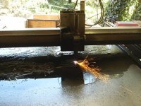
Accuracy: Well, the plasma process itself is subject to a bevel that happens depending on the cut travel direction. The bevel is between 3 and 8 degrees. On thinner materials, it all but disappears. When you get to about 1/8 inch, it becomes noticable. Another factor is the cut kerf. The kerf width depends on the height above the material you hold the torch, and the condition of the tip and other consumables. If you virtually drag the tip on the workpc, and your tip is new, it makes only about 0.025" (twenty-five thousandths of an inch) wide kerf. So inside corners are automatically filleted at .025" diameter, if they are drawn as square corners. If the software you use incorporates cutter compenstation, this kerf does not change the part. On my software (Master 5), it is not included so I am adding it with a different pre-processing program. This way, the cut line is fed to the controller card at 0.025" (or whatever you define) offset to the outside, so your finished part meets the original dimensions. On holes, the offset is to the inside of the line, to leave the hole the proper dimensions. There is of course some play in the motor/gear system, but that is much less than half the kerf width. Also, sometimes resonances can be set up by the rate and direction the motors are running, which can cause a slightly "knotchy" edge.
With all the above taken into account, except ignoring the bevel which is an unpredictable annoyance, I figure the accuracy overall to be within 0.020" of the desired final size, end to end of the part dimensions. This is of course way close enough for any welded assembly. Some of the parts this thing cuts out still amaze me and I have used it for over two years and maybe a hundred different parts now. Anything I draw now can have really nice stress-relieving and safety-providing curved edges, and the plasma cutter happily cuts them all perfectly, without question. /forums/images/graemlins/grin.gif
The motors I chose are plenty big enough for the mass they move, and the plasma does not resist motion like a router or mill would. Always remember that the power you need depends on the mass and the speed you want to move it. Tests have shown my system maintains accuracy a speed that is about 5 times as fast as the proper speed for the thinnest material I cut (sorry I cannot remember the exact units right now). So I have a fast speed for testing the layout of the part on the particular pc of metal I have chosen to throw on the table, and also the fast speed to move between cutting operations, but then it slows to a speed appropriate for the material I am cutting. The only time I have any issues with accuracy is if I happen to forget to connect the extra ground clamp to the workpiece. If the workpiece is not grounded seperately of the plasma ground clamp, it "radiates" interference which will sometimes get into the control loop and carry the torch off in a random direction. Thats always fun. /forums/images/graemlins/mad.gif
 
   / Plasma cutter, automation project #49  
Jim

Thank you very much for taking the time for a detailed reply. I'm trying to get a feel for automating my plasma cutter without over engineering the thing. Obviously the expensive linear guide blocks are fancy, but probably unecessary for the hobby fabrication setup. You have presented a very elegant, but simplified design for a gantry table.

The electrical interference may be improved by using a heavy braided copper ground strap. The braided form is more effective at reducing the high frequency noise. Also, covering the control cables with a braided shield, similar to a coaxial cable, may help. The control shield should be grounded at one end only. This provides shielding without allowing a current loop path.

Thanks

John
 
   / Plasma cutter, automation project #50  
I've read all your posts and I was wondering what software you are useing to create your drawings. I was also wondering if Master5 software allows z axis control for torch height control and if it can be used on the fly(while it is running). As I said before I'm useing the machine interface board from my
powermax 800 to control torch height, but I want to build a ox/acetelene system for cutting thicker metals. My current system will cut 3/8" thick but because of the lack of wall straightness I thought I would go with a reg torch. Also in an earlier post you talked about metal warping while cutting. I've included a picture of my machine cutting which shows the water I cut in. I discovered I could in water by accident. But when I realized I could cut in water I set my cutting grate in a 4x8 water tank and brought the water level up to the bottom of the sheet of steel. It really stopped the warping and it really stopped the amount of stuff it put in the air. It made the working enviroment a lot better. I was wondering if you where useing 14.5 degree or 20 degree rack and spur gears?
 

Attachments

  • 593012-table2.jpg
    593012-table2.jpg
    58.4 KB · Views: 794

Tractor & Equipment Auctions

AGT QK20R (A46443)
AGT QK20R (A46443)
2019 International DuraStar 4300 Dump Truck (A44571)
2019 International...
2014 Jeep Grand Cherokee Laredo SUV (A44572)
2014 Jeep Grand...
Kivel Mini Pallet fork Attachment (A47809)
Kivel Mini Pallet...
2025 Wolverine LL-12-78W Land Leveler Attachment (A47484)
2025 Wolverine...
2003 International 4300 Flatbed Truck w/ Liftgate - Inoperable - 7.6L DT466 Diesel Engine (A46878)
2003 International...
 
Top