Post-Frame Shed Build

   / Post-Frame Shed Build #1  

MtnManSK

Member
Joined
May 29, 2012
Messages
26
Location
SW Idaho
Tractor
Husqvarna Garden Tractor
Hello all,

I have been reading all sorts of useful information on this forum for months, and although my tractor is just a Husqvarna Garden Tractor, I decided to join and post about my experience building a post-frame style shed at our Cabin in Idaho. Hopefully someone will get some benefit from it as I have from reading others' posts.

I'll start with the background:

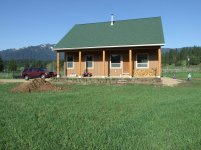
Last year, we had a modest cabin built on one acre in a beautiful valley in the Idaho mountains. We did a few pieces of it ourselves (some of the flooring, trenching and laying water lines and electrical conduit, etc.) but had a Contractor take care of most of it. We simply didn't have the time to do it ourselves during the 4-5 month window of time between spring's saturated ground and the next winter's snow. The cabin was a great success (see photo), and we enjoyed it on weekends through the winter, but we soon found out that we wanted to keep more toys up there than would fit under the porches.

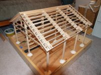
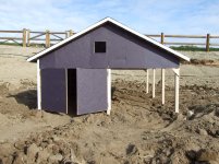
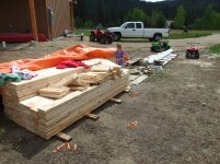
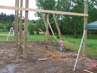
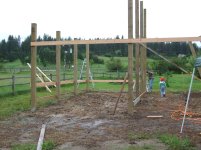
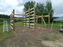
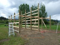
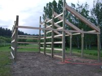
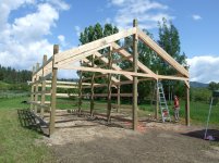
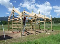
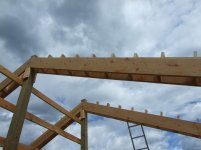
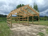
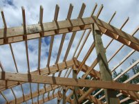
So, after a little convincing, my wife agreed that we should build a shed. We decided on 24'X24', with one half enclosed and the other side open with only roof cover. The open side would primarily be for firewood, canoe, ATV, and other large, hard to pilfer items.

To be continued . . .
 

Attachments

  • Cabin 012.jpg
    Cabin 012.jpg
    793 KB · Views: 2,059
   / Post-Frame Shed Build
  • Thread Starter
#2  
The Model:

I'm an engineer by training (Chemical Engineer actually), so it only seemed natural for me to build a model of the shed prior to trying to build it in full-scale.

I couldn't find any pre-drawn plans that matched what we wanted to build, and I didn't want to pay someone to draw it up. Also, we're lucky enough that the county where our cabin is located does NOT have building codes, so no structural engineering was required prior to getting a permit. I have some drawing software at work, but it just seemed more productive to figure it out as I went with small, cheap lumber.

As it turns out, small lumber is not as cheap as one might think, and I ended up spending about $100 on dollhouse lumber ordered online to get it done. I set the posts in modeling clay, used Super Glue for fasteners, and used construction paper for siding and roofing (cut to 3' scale width strips to match the ribbed steel I was planning on using). Everything was built on a 1:12 scale (i.e. 1" = 1'). See photos below (I set it up outside in the dirt for photos to send to the HOA for approval):
 

Attachments

  • 054.jpg
    054.jpg
    540 KB · Views: 1,056
  • Hula Hoop - Model Shed - Lawn Tractor 005.jpg
    Hula Hoop - Model Shed - Lawn Tractor 005.jpg
    651.4 KB · Views: 764
  • Hula Hoop - Model Shed - Lawn Tractor 014.jpg
    Hula Hoop - Model Shed - Lawn Tractor 014.jpg
    465.6 KB · Views: 442
  • Hula Hoop - Model Shed - Lawn Tractor 015.jpg
    Hula Hoop - Model Shed - Lawn Tractor 015.jpg
    323.7 KB · Views: 1,007
   / Post-Frame Shed Build #3  
More pls!
 
   / Post-Frame Shed Build
  • Thread Starter
#4  
The Estimate:

My wife and I both wanted to make sure before we went any further that we would actually be able to afford this project this year. So, I put together an estimate.

Once the model was built, I was able to make a pretty detailed materials list. I figured up the total number of board-feet of each type of lumber (treated members vs. #2 KD framing lumber). Then I went online and found some references for regional lumber prices per board foot, and picked one I thought was on the high side (to be conservative). I also measured and multiplied out the total number of "squares" of steel siding and roofing necessary. Again, the internet provided a rough price per square. Lastly, I utilized Lowe's and Home Depot's websites to find pricing on all of the miscellaneous parts (fasteners, foam condensation barrier, etc.).

I organized it all on a spreadsheet and totaled it all up, coming to around $4500 (not including road mix gravel to backfill the interior and build a lane to access it). In the end, this number turned out to be VERY close to correct.
 
   / Post-Frame Shed Build #5  
Looks great, very interesting build, I can't say I've seen anybody create a scale model of a shed before! Planning is always the key to having it come out well without any surprises, so whatever works for you.
 
   / Post-Frame Shed Build #6  
Very cool, and beautiful location!

Being an engineer myself, I can appreciate the planning and scale model. And I would also understand if "normal" people might think you're a nut job. As my wife tells me from time to time, "you engineers are just not normal". The trick is to have fun, learn, and exercise your brain a bit, and not worry about over-planning, over-analyzing, or over-building. When you start from scratch without prior experience, the engineering approach works well.
 
   / Post-Frame Shed Build
  • Thread Starter
#7  
Permitting and Material Procurement:

I sent pictures of the model to our HOA (the Cabin is technically in a subdivision), along with a plot plan I had drawn with MS Visio at work. We had to push right up to the minimum setbacks on the lot (10' side, and 20' rear) in order to fit it behind the septic drainfield. However, the HOA was gracious enough to approve it with no questions asked.

The county was very easy to deal with. Once they had their check, they rubber-stamped it and we were good-to-go.

I sent my lumber materials list (already completed for the estimate) to two local supply houses for bids. The bids came back almost identical, except one wanted twice as much as the other for delivery. We had no way to haul the 20' poles or the 24 sacks of redi-mix (due to sheer weight), so the lower delivery price got the bid. Unfortunately, lumber prices have increased this spring, so my estimate was several hundred dollars low on the lumber side. But, it didn't kill the project, so we went ahead and scheduled delivery for a Friday just before we would arrive for the weekend.

For the steel, we had been told by our cabin contractor that there was one local shop that used a much higher quality paint than the rest, so we didn't bother shopping around. I took measurements for each panel off of the model, and took that list to them for the bid. They actually came back several hundred dollars LOWER than my estimate, which offset the lumber overage nicely.

We borrowed my dad's 14' flatbed trailer and hauled it up there behind our half-ton Chevy ourselves. The total weight of the steel was only about 1500 pounds.

We had to re-stack almost all of the lumber since the delivery truck just dumped it in the mud, and of course we had to handle all of the steel to unload the trailer. However, we got it stacked and tarped so that it would be ready when the gound was ready to dig. I don't have a picture of the materials before we started buiding, but the one below gives you the idea.

Home Depot supplied all of the nails, bolts, and misc. supplies.
 

Attachments

  • Shed Construction 006.jpg
    Shed Construction 006.jpg
    818.5 KB · Views: 860
   / Post-Frame Shed Build
  • Thread Starter
#8  
Locating and Staking:

Knowing that we needed to be as close as allowed to the property lines, we started locating by setting the corner that would be closest. Then, we went parallel to the property line for 24' and set the next corner. From there, we had to calculate the hypotenuse (diagonal across the middle) and triangulate to get the next two corners squared-up. We used simple wooden stakes and staked out the location of each post.

Then, knowing that the stakes would have to move in order to dig the holes, we set stakes out away from the corners and stretched strings along the boundaries between these stakes. The strings could be removed for digging, then replaced for setting posts.

Lastly, I used my ATV sprayer to Roundup the native meadowgrass within the building area so we weren't trying to kill it after-the-fact.

All of this was done at least two weeks prior to breaking-ground. I wanted to have everything completely ready so that when we started digging, we could make fast progress.

I REALLY wish I had a picture of this available - if I can find one I'll edit the post and upload it.
 
   / Post-Frame Shed Build
  • Thread Starter
#9  
Digging Post Holes:

I went back-and-forth several times trying to decide what equipment to use to dig the post holes. I knew that, ideally, I needed about 18" diameter holes in order to be able to pour large enough "punch pad" footings for the posts. I also needed to get at least 36" deep to be below frost depth, but felt much better about 48" for a safety margin. The good news was that the ground on the valley floor up there is almost pure clay-silt. It's one of the only places I've seen in the entire state with NO ROCKS!!

Home Depot's tool rental center had a towable post-hole auger, but it's largest bit was 12", and I was afraid of under-sizing the footings that much and also having enough room in each hole to position the 6X6 posts if the holes weren't perfect. This option was, however, by far the cheapest.

On the other end of the spectrum, my boss at work gave me a number for a guy who has a post-hole auger mounted on the back of a Jeep. I'm not sure exactly how it works, but he claimed he can drill up to 24" holes VERY quickly. But, I really wanted to do this without hiring anyone, and he was going to charge full hourly rate for the drive up to the cabin (1.5 hrs) plus the work itself.

What we ended up doing was renting a Toro Dingo mini skid-steer with an auger drive and 18" auger (with extension to reach 4' depth) from a local equipment rental house. This was more money than the Home Depot option, but I'm VERY glad we did it because 12" holes would NOT have worked. The Dingo was pretty easy to tow behind our pickup, and was just enough machine to get the job done. It took about three hours to dig all twelve holes.

We knew exactly where to dig since we had already staked out the post locations. The biggest challenge was keeping the auger shaft approximately plumb while digging, so that the holes went straight down.

Here are a couple of pics. Yes, the operator is me.
 

Attachments

  • Shed Construction 005.jpg
    Shed Construction 005.jpg
    1 MB · Views: 698
  • Shed Construction 003.jpg
    Shed Construction 003.jpg
    800 KB · Views: 804
  • Shed Construction 001.jpg
    Shed Construction 001.jpg
    918 KB · Views: 691
   / Post-Frame Shed Build
  • Thread Starter
#10  
Pouring Footings:

After the holes were dug, we wanted to get the footings poured that same evening so that they could set-up for almost 24-hours before we stood the posts up on them.

So, we hurried-up and wheelbarrow-mixed one sack at a time, pouring one 90-lb sack in each hole. That gave about a 5" thick pad. I knew 6" was ideal, but the clay was VERY compact down that deep, and it was so simple to just put one sack in each hole that we just did it that way.

It was getting late, so we didn't get any pictures of this step.

One thing that was a little odd was that we had dug all of the holes to almost exactly the same depth (about 48"), but only two out of the twelve had some water run into them from the water table being that high. I'm not a hydrologist, but I'd never heard of the water table running in "veins" so that one spot will have water and another at the same depth only 8 feet away won't.

Regardless, it bothered me a little to pour concrete into water, but I've read that it only affects the strength of the SURFACE of the concrete, which we don't care about way down underground anyway. Hopefully this is true.
 
   / Post-Frame Shed Build #11  
Wow, what a well structured approach (and thread!).

As an engineer myself I can really appreciate your thought process. But to build a scale model of a freakin pole shed!?!? hahaha! That's wayyyyy too much time (and $$) into just the planning stage. I am using google sketchup to design my own shed that I'll build this summer, for free.

Looking forward to the rest of the thread and results!
 
   / Post-Frame Shed Build
  • Thread Starter
#12  
Standing the Posts:

The next morning, we had to un-stack and re-stack the lumber to get to the treated posts which were on the bottom (intentionally, since the dirt won't hurt them).

We have (12) 6"X6" posts, (8) at 14' long, and (4) at 20' long. My wife and I could handle the 14 footers with moderate effort, but simply picking up and carrying the 20 footers was about all she could do (and worked me pretty hard as well). We're pretty small folks . . .

Around lunchtime, my wife hauled the Dingo back to the rental shop and went to a Dr.'s appt. in town while I stayed up at the cabin with our daughters (age 3 and 5) waiting for the footers to set-up a little longer.

When she got back that afternoon, we set to work standing the posts. After the difficulty we had moving the posts around, I knew we were going to need some mechanical advantage to raise them up vertical and slide them down into the holes. So, I set up a pretty ridiculous-looking rig with a 10-foot heavy-duty stepladder as a crane positioned over the hole. I tied the back-side of the ladder off to our ATV as a counter-weight, and we laid one of the 14' posts down perpendicular to the ladder on the opposite side. A 2X6 scrap served as a "slider" board at the back of the hole for the post butt to slide down as we raised it. Then, we connected a come-along winch from the top of the ladder to about 2/3 the way up the post.

Again, I wish I had gotten a picture of this, but we were so focused on what we were doing, that we forgot to pull out the camera.

This contraption actually worked pretty well for the first 14' post. Raising the post only took a few minutes, vs. the 10-15 min. it took to set up the rig. However, the next post we tried was a 20 footer. Those extra 6 feet made a HUGE difference, and we barely got it upright. The "crane" was a little too short, and we ended up having to muscle it up most of the way, which was not very safe or easy for one short man and his wife.

Here's where the story gets a little better. Apparently, two of our neighbors had been watching from the next house while we stood those first two posts. One is jack-of-all trades who isn't much bigger than me, but has done LOTS of construction work. The other is ex-military, and probably has nearly a foot and about 100 pounds on me. They claimed that they couldn't stand to watch us struggle any more, and between us three guys, we simply walked-up the rest of the posts in a matter of about 15 minutes.

This is what I love about these small mountain communities. Folks show up without being asked to help with the "heavy lifting" and don't ask for anything in return. We took them both a six-pack of their favorite beverage later anyway, but I can't tell you how much we appreciated their help just when we needed it most!!
 

Attachments

  • Shed Construction2 001.jpg
    Shed Construction2 001.jpg
    842.4 KB · Views: 458
  • Shed Construction2 003.jpg
    Shed Construction2 003.jpg
    907 KB · Views: 476
   / Post-Frame Shed Build #13  
Really enjoyable and interesting. Beautiful area..Thank you, Jim
 
   / Post-Frame Shed Build
  • Thread Starter
#14  
Plumbing and Setting Posts:

We decided to set the four corner posts in place first, and follow-up with the intermediate posts, installing some framing as we went so that we could remove and re-use braces.

We had a 58" carpenter's level that worked okay for plumbing the posts, but our neighbor with construction experience came to the rescue again with a much better tool. He had an extendable level that must have gone out to about 16' at its full extent. This allowed us to check the posts from top to bottom instead of just a few feet near the bottom, eliminating possible error due to slight curvature of the post.

He also let us borrow a set of "turnbuckle braces". These can be nailed to the end of a brace and staked to the ground so that the braces become infinetely adjustable in length. By installing two of these perpendicular to each other on a post, we could finely adjust them until the posts were virtually perfectly plumb. Again, we greatly benefited from someone else's generosity with tools and expertise. We can only hope to return the favor someday.

With plumbing them made so easy, it turned out that positioning them was the tough part. We knew where they needed to go based on our string lines, but once they were stood up, they DID NOT want to slide around on the concrete footings. We ended up having to wiggle and "walk" them close prior to bracing, and then use the back of a 6 lb maul to "bump" them the last little bit. We still weren't able to do better than about 1/4" precision.

Once they were positioned and braced, we dumped another bag of concrete (dry) in around their bases, and backfilled the rest with native soil, tamping VERY thoroughly as we went. This was long, hard hand labor, but we were able to get them set really tight.

This process took an entire day, plus another hour or so to get all 12 posts. As you can see, the weather was a little moist for part of that time, but we just "slogged" through it.
 

Attachments

  • Shed Construction 009.jpg
    Shed Construction 009.jpg
    818.9 KB · Views: 817
  • Shed Construction2 006.jpg
    Shed Construction2 006.jpg
    837.9 KB · Views: 359
  • Shed Construction2 005.jpg
    Shed Construction2 005.jpg
    699.1 KB · Views: 398
   / Post-Frame Shed Build
  • Thread Starter
#15  
Sidewall Framing:

The sidewall framing consisted of a treated 2X6 skirt board and 2X6 girts on 24" centers around the enclosed side of the shed. We also put a single run of 2X6s just under the eaves on the open side.

As you can see in the previous post, we did some of the framing concurrent to setting the posts so that we could move the braces and re-use them.

The first step was to set a "zero" elevation for the entire structure. This would ideally be done with a spinning laser level that could hit all of the posts at once. However, we didn't have access to one and didn't want to invest in one powerful enough to work outdoors just for this project.

So, we simply went to the post with the highest natural grade (back corner), and tacked on a treated skirt board about 1.5" above grade (sitting on a 2X6 block, to be exact). Then we set the long level mentioned above on it sideways, adjusted until it was level, and tacked it onto the next post. We continued this process of tacking, leveling, and nailing the skirt boards to all of the posts around the enclosed side of the shed. As a cross-check, we laid the level on the skirt boards across the middle of the enclosed side on the opposite end of our starting point. This verified that we had not drifted off of level on one side vs. the other.

Next, we measured up and marked for the height of the eave girts and nailed them on. For the open side, we had to again use the level to position them on the posts. Once we had one skirt board or girt on each post (and all were level), we had a reference point for all other framing.

For the intermediate girts, we cut two blocks at 18.5" each, and used them to space out each run without measuring every post. That went really fast.

Working our way up from the bottom, we could climb the framing while carrying the boards up and nail them in place. We didn't even need ladders.
 

Attachments

  • Shed Construction 010.jpg
    Shed Construction 010.jpg
    835.9 KB · Views: 436
  • Shed Construction 011.jpg
    Shed Construction 011.jpg
    756.3 KB · Views: 539
   / Post-Frame Shed Build
  • Thread Starter
#16  
Rafters:

Most Post-Frame buildings these days utilize pre-fab trusses for the roof support (I have a shop at home that was built that way). However, with a run of posts down the middle of this shed, I didn't think it was necessary to use trusses, especially when I was pretty sure we would need a crane or other high-lift device to set them.

Since our span is only 12' on each side, I used deck beam tables and determined that double 2X12s could provide a load rating of 50 lbs/ft2. With a steel roof on a 6:12 pitch, I'm quite certain that the snow will slide off LONG before it gets that heavy. 50 lb/ft2 would be the upwards of 9.25 inches of snow-water equivalent stacked up on the roof. The area only gets about 25 in. of precip. in an entire YEAR!

We weren't sure how difficult it might be to raise the 2X12s manually, so we decided to cut and nail blocks onto the posts to support the rafters while we nailed them in place (so we wouldn't have to rely on our muscles for as long!).

A little trigonometry and a few miter saw cuts later, we had the blocks installed (you can see them in the previous post's photos).

We didn't order any extra 2X12s, so we were VERY careful about measuring and cutting them. Incidentally, the calculator said that each rafter should be 13' 5". Actual measurements (by stretching a flexible tape from the peak block to the eave block) came in within a 1/2" of that (except for the rear set, where the peak ended up nearly an inch off to one side). Not too bad for a couple of amateurs, if I may say so myself.

On the second try, we figured out a pretty easy way to hoist the rafters into place. We would stand them up next to the peak post and Mrs. MtnMan would climb to the top and guide them as I lifted the entire thing vertically. Once the top end was sitting on the block, I would carry the bottom end across and up toward the eave-post, then carry it up the ladder and set it on the lower block. The eave girt prevented it from sliding down and away. Then I just grabbed the nail gun and tacked it on. We could measure, cut, and install one every ten minutes that way.

After they were installed, I used a long boring bit on a heavy-duty drill (borrowed) to drill 1/2" holes in each post-rafter assembly. Into these I installed 1/2" bolts to firmly secure the rafters to the posts.

Lastly, she cut and installed some short knee-braces on the open-side posts to add a little stiffness. I think they look pretty cool, too.

At that point, we had run out of time for the long weekend. We were pretty happy with the progress, though, and will be back up there in two weekends to work some more.

Next steps: cutting the excess off the post tops, start roof framing. I'll update in a couple of weeks.
 

Attachments

  • Shed Construction 015.jpg
    Shed Construction 015.jpg
    700.5 KB · Views: 519
  • Shed Construction 018.jpg
    Shed Construction 018.jpg
    750.8 KB · Views: 785
  • Shed Construction 017.jpg
    Shed Construction 017.jpg
    692.5 KB · Views: 570
   / Post-Frame Shed Build #17  
Sidewall Framing:

The first step was to set a "zero" elevation for the entire structure. This would ideally be done with a spinning laser level that could hit all of the posts at once. However, we didn't have access to one and didn't want to invest in one powerful enough to work outdoors just for this project.

So, we simply went to the post with the highest natural grade (back corner), and tacked on a treated skirt board about 1.5" above grade (sitting on a 2X6 block, to be exact). Then we set the long level mentioned above on it sideways, adjusted until it was level, and tacked it onto the next post. We continued this process of tacking, leveling, and nailing the skirt boards to all of the posts around the enclosed side of the shed. As a cross-check, we laid the level on the skirt boards across the middle of the enclosed side on the opposite end of our starting point. This verified that we had not drifted off of level on one side vs. the other.

Nice build and thread.

What you did works great, but next time you run into this problem, may I recommend you invest in a roll of builders twine and a line level ($2.99 for a pack of 2). Not as sexy as a rotary level, but does the job.

[ame=http://www.amazon.com/Kapro-440-08-Line-Level/dp/B001N3H1P0/ref=sr_1_2?ie=UTF8&qid=1338322604&sr=8-2]Kapro 440-08 Line Level: Amazon.com: Industrial & Scientific[/ame]
 
   / Post-Frame Shed Build #18  
Excellent job and thanks for the documentation in your thread. I build a 20x28 ft post frame shed a few years ago and went through the same process you used. Fun and games:D
 
   / Post-Frame Shed Build
  • Thread Starter
#19  
Rafter Blocking:

After a two-week hiatus, we were back at the Cabin last weekend and made a little more progress on the shed.

The first step was to haul the chainsaw up to the top of the posts and cut off the excess. I left enough to nail 2X6's to and tried to angle them with the roof pitch. However, not being a logger by trade, running the chainsaw sideways, at an angle, on a ladder, AND at about shoulder level proved difficult for me. I wasn't able to cut them exactly on the marks, but luckily it doesn't really matter because they will all be covered and nothing rests directly on the tops.

Next we needed to install the rafter blocking. These are 2X6s sandwiched between the rafter pairs and sticking up so that the purlins can be nailed to them and held upright and on edge. They needed to be 16" o.c. and approximately perpendicular to the rafters. Add to this the fact that most of the 72 blocks would need to be installed while on a ladder, and I knew that we would need something to ease the process. Thus, I built a simple "jig" that would hold the block in place (16" away from the one above, and perpendicular to the rafters) while we nailed it from one side. Then, the "jig" could be moved one block down for the next one. (see photo below) Last, we came back and nailed the blocks from the other side of the rafter pair.

This worked for all except for the top and bottom blocks, which had to be held in place by hand. However, those were a little easier because we had posts/framing to hang on to. In all, the blocking took an entire afternoon and didn't really look like much when it was done. But, it made the next step much easier . . .
 

Attachments

  • Shed Construction 3 005.jpg
    Shed Construction 3 005.jpg
    1,012.8 KB · Views: 465
  • Shed Construction 3 003.jpg
    Shed Construction 3 003.jpg
    253.5 KB · Views: 392
  • Shed Construction 3 002.jpg
    Shed Construction 3 002.jpg
    683.7 KB · Views: 578
Last edited:
   / Post-Frame Shed Build
  • Thread Starter
#20  
Purlin Installation:

Building this shed in "snow country", we decided to go a little on the overkill side with roof framing. So, planned for 2X6 purlins standing on edge, 16" o.c., spanning less than 8 feet. The only downside to this is that we're adding a little more dead-load than is necessary to the rafters, but I REALLY didn't want the roof metal sagging if we got a big snow that didn't slide for a few days.

We started with the middle bay and simply nailed the 2X6X8' boards onto the blocks, working our way from the bottom up. As we went up, we created a framework we could crawl/sit on to work. This went REALLY fast.

Since our roof metal comes in 3' coverage panels, we decided to make the total width of the roof (gable to gable) 27'. This would give us 18" overhangs on each end and prevent us from having to "rip" a panel lengthwise. We were trying to minimize cutting the steel panels.

Thus, for the front and back bays, we needed to measure and cut for each purlin so that the total roof dimensions would be correct. This took a little longer, but with both Mrs. MtnMan and myself working on it, we knocked it out the course of about half a day. We helped ourselves a little by measuring and writing down all of the lengths for a bay in one trip up onto the roof/ladder, then cutting them all, then installing them all. That required a little more organization, but reduced the amount of climbing significantly.

The result wasn't perfect, but with a little trimming in place with a circular saw, I think the facia boards will go on okay (and relatively straight).

That was as far as we got in a regular weekend (with some more rain and a few other obligations). We probably won't be able to do any more significant work until the weekend prior to the 4th of July. Next steps: outriggers and facias.

FYI: I thought I would mention here that two tools have proven themselves ABSOLUTELY indespensible in this project so far:

1) A Porter Cable FR350 framing nailer. We picked it up used (barely) for $90, but I'd have paid double that if I couldn't find a used one. It's extremely reliable, easy to use, and saves a LOT of hammer-swinging. It doesn't even use much air, running just fine on my small pancake compressor. The only downside is it's just a little heavy.

2) A Chicago Electric 10" sliding compound miter saw. We ordered one of these from Harbor Freight (made-in-China superstore) for $100 with a coupon. The first one showed up broken, so we exchanged it at the local Harbor Freight store, and this one has been flawless. It makes regular square cuts SO much quicker and easier than a hand-held circular saw. It also had enough capacity to cut our 2X12 rafters at the 26.5 deg. miter angle necessary. We set it up on planks and saw-horses under a shade canopy, and it has been VERY nice.
 

Attachments

  • Shed Construction 3 012.jpg
    Shed Construction 3 012.jpg
    710.1 KB · Views: 520
  • Shed Construction 3 013.jpg
    Shed Construction 3 013.jpg
    757 KB · Views: 1,222
  • Shed Construction 3 014.jpg
    Shed Construction 3 014.jpg
    432.9 KB · Views: 694
Last edited:

Tractor & Equipment Auctions

PALLET OF 15 4 X 8 GROUND PROTECTION MATS (A58214)
PALLET OF 15 4 X 8...
2019 CATERPILLAR 259D SKID STEER (A60429)
2019 CATERPILLAR...
2018 CATERPILLAR 930M WHEEL LOADER (A60429)
2018 CATERPILLAR...
JOHN DEERE 4450 TRACTOR (A59823)
JOHN DEERE 4450...
Craftsman 42 Inch Riding Mower (A57454)
Craftsman 42 Inch...
Honda EM3500S Portable Gasoline Generator (A59228)
Honda EM3500S...
 
Top