shaeff
Veteran Member
- Joined
- Oct 27, 2015
- Messages
- 1,046
- Location
- Hudson Valley, NY
- Tractor
- MF Utility 35 Gasser, JLG LJ500
Some of you may remember my thread from a few months back:
http://www.tractorbynet.com/forums/...c-vintage/347197-early-60s-mf-35-utility.html
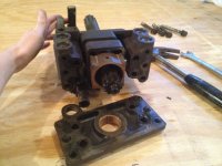
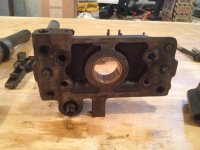
Well, life got in the way for a while and the tractor was on the back burner for a few months while I sorted out other issues. To sum up my issue from the last thread (which is way long at this point), I bought a MF35 Utility, got it all up and running except the rear hydraulics did not function. I came to the conclusion that the lift cylinder studs snapped off of the lift cover assembly. I finally got around to opening up the rear of the tractor on Saturday, and that's exactly what happened. I'm not sure whether it's due to water ingress, or the previous owner lifting something that was way to heavy and possibly bouncing it over a bump. The fact remains that the lift cylinder is indeed snapped off, all four studs. It otherwise seems to be in good condition.
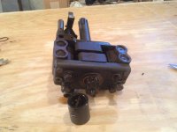
I have the factory AGCO manuals, but one of the exploded diagrams is still leaving me with a question concerning the hydraulic pump. Considering how easy it was to remove the lift cover, I'm tempted to fix the lift cylinder and put it back together to see if it all functions, but wanted some opinions first.
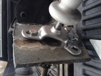
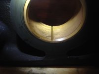
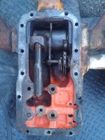
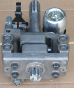
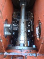
Third picture below shows the innards of the tractor as seen from the rear. The lift cylinder was sitting on top of the main drive coupler, and the rock shaft was hanging down. In the upper right corner, all the way down in front of the hydraulic pump, I found a very long spring. It looks as long as the springs used for the lift/draft controls. I know there is a spring in the hydraulic pump down in that area as shown in the second picture I got from Google. This spring I found is easily 8-10" long. Is it likely that it came from the lower left side of the hydraulic pump picture?
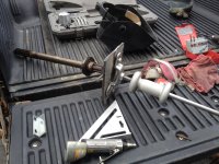
I'll have to try and drill out the four broken studs, as the lift cylinder appears otherwise undamaged. I'd like to reuse it if possible. Aside from the usual o-rings here and there, is there anything else I should replace inside? Can I fill this thing with some diesel (to continue to flush the system) and run it with the lift cover off to see if the pump works? Without the stand pipe bolted in, I'm betting it would make a huge mess, right?
Thanks, all!
http://www.tractorbynet.com/forums/...c-vintage/347197-early-60s-mf-35-utility.html
Well, life got in the way for a while and the tractor was on the back burner for a few months while I sorted out other issues. To sum up my issue from the last thread (which is way long at this point), I bought a MF35 Utility, got it all up and running except the rear hydraulics did not function. I came to the conclusion that the lift cylinder studs snapped off of the lift cover assembly. I finally got around to opening up the rear of the tractor on Saturday, and that's exactly what happened. I'm not sure whether it's due to water ingress, or the previous owner lifting something that was way to heavy and possibly bouncing it over a bump. The fact remains that the lift cylinder is indeed snapped off, all four studs. It otherwise seems to be in good condition.
I have the factory AGCO manuals, but one of the exploded diagrams is still leaving me with a question concerning the hydraulic pump. Considering how easy it was to remove the lift cover, I'm tempted to fix the lift cylinder and put it back together to see if it all functions, but wanted some opinions first.
Third picture below shows the innards of the tractor as seen from the rear. The lift cylinder was sitting on top of the main drive coupler, and the rock shaft was hanging down. In the upper right corner, all the way down in front of the hydraulic pump, I found a very long spring. It looks as long as the springs used for the lift/draft controls. I know there is a spring in the hydraulic pump down in that area as shown in the second picture I got from Google. This spring I found is easily 8-10" long. Is it likely that it came from the lower left side of the hydraulic pump picture?
I'll have to try and drill out the four broken studs, as the lift cylinder appears otherwise undamaged. I'd like to reuse it if possible. Aside from the usual o-rings here and there, is there anything else I should replace inside? Can I fill this thing with some diesel (to continue to flush the system) and run it with the lift cover off to see if the pump works? Without the stand pipe bolted in, I'm betting it would make a huge mess, right?
Thanks, all!
")