The best way for you to see how this would work is to buy one of these timers and then play with it a bit.
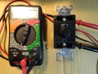
Do you have a volt/ohm meter ? If not, you will need one to see that operation of the switch.
View attachment 710097
There is no "middle" position. The terminals are NO (normally Open) and NC (Normally Closed) In this illustration above, the input terminal is in contact with the top terminal, so that would be the NC connection.
In your application, you would connect the input terminal to the wire that goes to your engine on/off switch. You can leave the engine on/off switch wired as is, just connect the input terminal to the same wire.
Then the bottom terminal would be connected to the engine ground.
When you set the timer, lets say for an hour, when the hour is up, the contact will switch to the NO terminal and stop the engine.
View attachment 710098
This should give you and idea on how to wire up the timer.
Richard