QRTRHRS
Elite Member
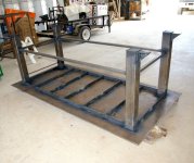
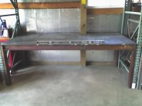
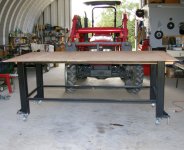
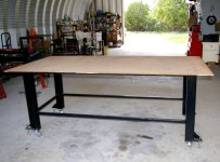
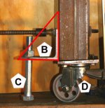
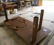
I have four lengths of six inch flanged ductile iron pipe just waiting for some I-beam and a thick plate to make a table. If and when I get some decent space to set up, I will set up one end with alternating square tubing instead of solid table. That is, open space equal to the tube stock so I can slip hold down clamps through the gap.
That limits welding to the table but I would still do that as required. I don't wax my tractors either. Heck, if I wax my vehicles once a year, it would be a "weak moment". LOL!
That limits welding to the table but I would still do that as required. I don't wax my tractors either. Heck, if I wax my vehicles once a year, it would be a "weak moment". LOL!
")