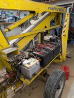
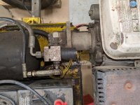
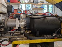
On the photo of gas engine and pump shows the unloading valve. By the shape of the coil it could be a Delta Power valve. If it is the name should be molded on the coil. If schematic is correct it is Normally closed and energized to open allowing flow in the side ports and out the nose to tank.
The DC unit probably has the valve in that block between the motor and reservoir.
Thanks, now I understand.
If I understand the operation, the dump valve is energized when I push the button that turns on a hydraulic pump (either motor or gas engine, it doesn't matter), but then something has to deenergize it so it closes. I'm guessing the flow switch is somehow doing that, even though it isn't shown on the logic diagram. So as soon as flow starts, power is removed from the dump valve.
The problem I'm chasing is that when I push the hydraulic button that should turn on the DC motor, it doesn't come on. I've traced it to the wire on the control board that goes to the contactor on the motor, and it's not raising 12v when I push the button, so something in the logic circuit is preventing it.
Here's the logic diagram if you have time to look at it. The resolution isn't great unless you have a larger monitor. Look at the far left two logic streams, one is labeled "DC Motor Run", the other is labeled "Pump Dump". The top horizontal line on drawing is +12v, the bottom line is ground. The connection point labeled "101" always has 12v, in order for the motor to run the connection labeled "14" must be 12v, but it's not. The connection point labeled "116" has 12v, which is energizing the dump valve. My machine doesn't have that device labeled "Battery Management" with the dotted line around it, so connections 14 and 114 are jumpered together.
So my problem comes down to figuring out why that relay labeled "RL8/1" (which is almost impossible to read) isn't closing and putting 12v on connection 114.


