wiring for welding

   / wiring for welding
  • Thread Starter
#21  
Another interesting tidbit for those thinking a ground is needed, I just removed the cover to look inside the unit. The ground from the plug is screwed to the case. As far as I can see there is no ground attaching to the transformer unit.
 
   / wiring for welding #22  
KubotainNH, I have a welder similar, possibly identical, to yours. Had it since 1967. Many facets to your question. The size of your projects is less important than the size electrodes you'll be using. That determines the output range. My welder is wired with 8/3 cause I got the wire for free. If you never burn bigger than 1/8" rod you can get by with 10/3 on a 30 amp breaker forvever and stay in the 100% duty cycle. If you buy bigger rods they just won't work very long without tripping the breaker. You're right about the neutral/ground. The welder doesn't need it but you run the risk of a short energizing the cabinet & zapping whoever touches it.
If you buy an ohm meter to check voltage, buy two because it'll burn up on the first attempt unless it's a good one, get a voltage meter to check voltage. I suspect you already knew that. :D
Absolutely set up good ventilation in your basement. Welding fumes can cause serious health issues. Cartridge respirators are cheap and effective but don't protect the rest of the household. MikeD74T
 
   / wiring for welding #23  
KubotainNH said:
Wow, this brought alot of viewpoints to this thread. Let me answer some things and make some points. First of all my house was built in 2003 with me as the GC and doing a bunch of the work. I have been doing electrical work for 25 years or so and went to school for electronics so am not clueless when it comes to this stuff. I've never wired a 220 line for a welder which is why I started the post. BTW, I would never put a breaker that is rated for more amperage than the wire. My welding projects are small so by no means will I max the thing out. It does seem funny to me that the welder has 12 guage wire but to be safe I need to use 6. Lastly, who's time is this site set to? :)

GMT.....It's based on the zero merdian that passes through London, England, or close to(GREENWICH MEAN TIME)....subtract 5hrs for Eastcoast. and 8hrs for the Westcoast this time of year. It is also used for all navigation too, and is the absolute correct time for the entire world for all the time zones with the atomic clock, I think?
 
   / wiring for welding #24  
kennyd said:
NEC article 630 specifically refers to welding machines and shows tables about how the de-rate conductors for use with them. I will say again, it has to do with duty cycle.
PM member "inspector507" if you don't believe it:D:D


I think you may be correct but is he going to wire the welder into the box directly? he is putting a plug in that will be used to weld with today, tomorrow someone may plug a oven/stove or ?? into it when there is a outlet installed only items able to plug into that outlet have that type of plug on the end of them. if it is a 20 amp 120 volt device it has a plug that has one of the poles (hot lead) turned 90 degrees from a standard 15 amp 120 volt plug.

same goes for any DEVICE a welder is a device what is plugged in. that welder manufacture determines what it is rated at for usage and has to put a/an appropriate plug onto that device. if they put a 15 amp plug on it the device needs LESS THAN 15 amps. If they put a 20 amp plug on it it means it needs 15 to 20 amps if there is a 30 amp plug it means 20 to 30 amps are required... get my drift... that is WHY there are different plug designs with different prongs so you can't plug a 50 amp device into a 120volt 15 amp wall outlet....

NOW ask any welder person out there if they have EVER followed the duty cycle warning on the machines they are running??? I've done a fair bit of welding (as in welded for a job for years.) SO if you are welding you keep going until you are done, stopping & starting only when rod is out or you need to move to get a better angle...


mark m
 
   / wiring for welding #25  
In 220 volts the sine wave is positive on one wire and negitive on the other leg at one instance (note the polarity changes 60 times a second (hence 60 hertz)and will switch polarity on the next cycle.


The current moves from negative to positive all the time (this is electron flow)
so actually the same electron keeps being pushed and pulled as the sine wave advances in time.

http://www.sprags.com/images/mainpower_sine_wave.jpg
tom
 
   / wiring for welding #26  
tommu56 said:
In 220 volts the sine wave is positive on one wire and negitive on the other leg at one instance (note the polarity changes 60 times a second (hence 60 hertz)and will switch polarity on the next cycle.


The current moves from negative to positive all the time (this is electron flow)
so actually the same electron keeps being pushed and pulled as the sine wave advances in time.

http://www.sprags.com/images/mainpower_sine_wave.jpg
tom

one correction, while in theory this is correct in most applications the sign wave is out by 1/3 not 1/2 as in most power situations the system is derived from a 3 phase power each of the phases being out by the 1/3.

even most homes are powered from incoming power that has a 3 phase/legs and one neutral/ground wire system.

When measuring voltage you have 2 ways to measure it, True RMS (root mean square) voltage and PEAK TO PEAK voltage. On a home system you will have ~175 volts peak to peak, but only 120 volts RMS (RMS is basically the AVERAGE of the power under the curve) that is Line to Neutral/ground voltage.

you are 100% correct on the electron flow from - to +, but that is in a DC system, in AC system it doesn't go any where just back & forth :) wonder that thing don't wear out the rug lol... besides that why do I have to pay the electric company if I'm only using the same electrons??? Maybe they should call it rental fee instead of a consumption charge hahaha...

mark
 
   / wiring for welding #27  
Mark around here there is only single phase wiring in most houses.
and it is 180 degrees out of phase


Single-phase power systems : POLYPHASE AC CIRCUITS


Scroll down to the bottom of page for single phase picture text is very good too

I haven't found a good 3 phase (120 degrees shift) diagram on line but I will keep looking

found it
Three-phase power systems : POLYPHASE AC CIRCUITS

after looking at this whole page it is impressive ther is alot of information on them.

Volume I - DC : All About Circuits

tom
 
   / wiring for welding
  • Thread Starter
#29  
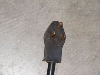
Phew, I walk away for a little while and wow.... I do not plan on using rod any larger than 1/8". I think the plug is the same as my range and that is wired with a 40 amp breaker done professionally for the local code. When I have some time I will verify the plug and maybe post a picture. The welder will not be directly wired to a breaker panel, it will use the plug that came with it. Thanks for all the posts.
 
   / wiring for welding #30  
Wow, not to step on anybodies toes but there is a lot of bad advise here.

One of the purposes of a circuit breaker is to prevent the wiring from overheating. If you use #10 wire and land it on a 50 Amp breaker, at high current draw the wire will overheat before the breaker trips, and you have a potential fire.

Always size the wiring to the breaker, consult the tables in the NEC for proper sizing.
 

Tractor & Equipment Auctions

(4) Drums of Mixed Fabric Softener/Detergent (A51573)
(4) Drums of Mixed...
New/Unused Fuel Pump with 50ft of Hose (A51573)
New/Unused Fuel...
2016 Ford Fusion Sedan (A50324)
2016 Ford Fusion...
2008 New Holland B110 MFWD Loader Backhoe (A53472)
2008 New Holland...
2024 Scag V Ride XL (A51573)
2024 Scag V Ride...
Guard Rail Pieces (A51692)
Guard Rail Pieces...
 
Top