OP
eepete
Platinum Member
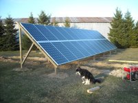
The Unirac has you attaching to one side for the rail, and another side for the post mounts. So the holes in the ground don't quite line up. I didn't catch this, so I have a little off-angle tilt to the posts. Fortunately, I got a bunch of neoprene washers that I used to give the system some slop tolerance and to separate the face of the stainless steel washer from the extruded aluminum angle (long term galvanic concerns).
If I could have found a good source of aluminum C channel here, I would have put 6 holes per 12 panels. The channel would be held up with 1/2" stainless threaded rod. Instead, I have 18 holes per 12 panels and used 3/8" stainless threaded rod. You can see where the install time would go down, leveling would be easier, and the whole array would be more symmetric. I had problems with the 3/8 rod bending as I mounted things. All the usual first-time discoveries and like most project only when you are done do you really know how to do it.
The software is part of the automation stuff I'm working on. For the solar, I'm going to have to make a new current sense board. The inverter has about an amp of imaginary power you can see at night, presumably from the EMI filters in the unit. So I'll be taking a chip made for power company residential meters and making the equivalent of a meter. Then I'll have real power, power factor, and harmonic distortion. The cheaper current transformer only sensor is OK for lots of stuff, but with the PV you're talking big power and big money so there is more accuracy needed. Of course, since the PV array cost so much, the extra cost of an accurate reading system is not too bad.
All the inverter manufactures are trying to make money selling you the ability to see what your system is doing. But it's not an open system, there are no standards. So it's yet another stand alone hack like the weather stations and HVAC systems- no integration possible. The extra cost they charge for the inverter add-on is on the order of $400 and up, which is more than enough to cover whatever I end up building. There are also some interesting isolation problems since the panels are outside, have area, and can be hit by lightning. For battery current, I've got a nice instrumentation differential amplifier that can take 4mV and make it 4V (that's at max gain- gain is jumper programable) so a small 1 milliohm shunt on the low side where the batteries connect to ground would work. There are some high side current monitoring systems out there, but the single chip ones don't like big voltages- problem for another day. But what fun problems!
Pete