Question about steel strength??

   / Question about steel strength??
  • Thread Starter
#161  
I decided to make a full scale model of this attachment
out out of scrap lumber. I'm really glad that I did. It allowed
me to see relationships (that I would not have other wise seen)
and make the corrections before sending this to the welder.

Being that I am not familiar with working with metal, I can use
some help in designing a way to mount the FEL brackets to the frame.

I am now using Creamer's fork design with square bottom rail and wrap
around c-clamp. See Post #137.

The upper frame is 2x2 tubular and the bottom rail is 3x3 tubular steel.

My goal is to make the FEL plates removable. They will add approx. 50lbs
to the attachment that I would like to be able to remove when not in use.

Sending 8 photos to give you an idea what it looks like
and what I thought may work?

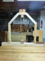
Photo 1 is an overall front view showing the FEL mount on the right.
P1050725.jpg

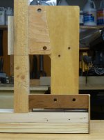
Photo 2 shows a close up view of the upper and lower welded mounts
and the FEL plate in place. These would be bolted together.
P1050726.jpg


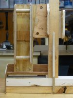
Photo 3 shows the 3x3 with a welded end plate on the outside. An angle iron is then welded
between this plate and the 2x2 tubular frame upright. This is the bottom support
for the FEL plate. Note that the angle iron is supended above the
3x3 rail. This space will allow the fork c-frame to be inserted and mounted in this outside
area. This will allow for complete adjustability from the center hitch receiver, all the way to
the outer welded end plates-minus the 2" space taken by the frame uprights.
P1050727.jpg

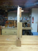
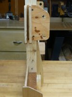
Photo 4 shows a side view of the 3x3 end plate. and the FEL bracket, above it.
P1050728.jpg

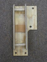
Photo 5 shows the lower link mounting plate that I modified to create a channel
where the FEL plate is inserted into the channel.
P1050729.jpg

Photos 6&7 are of the FEL brackets welded to the mounting plate.
P1050730.jpg
P1050731.jpg

Photo 8 is a close up of the lower angle iron mount and the space for the c-clamp
to fit into. Note the verticle steel welded to the 2x2 upright as well as the 3x3 rail.
This may add strenght to the frame and rail design/torsion?
P1050732.jpg

Well, there it is. Feel free to completely re-engineer.:thumbsup:
 
   / Question about steel strength?? #162  
Yes it is preferable to have the bend line perpendicular to the way it comes off of the mill. The elongated grain structure will bend more without breaking.
While cold rolled is slightly workhardened it is usually not significant to affect bending much. Hot rolled is typically thicker material and often has more impurities in it. Hot rolled also has some scale left over from oxidation due to it being hot in air which creates a surface condition that can lead to to cracking. I prefer to use cold rolled for bending. Also, it is best to try to stay away from a 1t bend, i.e. bend radius = the material thickness. 2t makes a lot of difference.

Not quite.
The amount of impurities is the same regardless of how the steel is formed unless it is folded & rolled which makes it true wrought iron.
However the distribution of impurities withing the structure will be different.
 
   / Question about steel strength?? #163  
You probably cannot measure the difference in tonnage on thin materials but the real problem is cracking at let's say a 1 D bend. Cold roll because of it's hardened surface from being cold worked does not like to be bend. You can grind and or polish the formed ends to minimize the cracking before bending and or forming and or heat the part minimize cracking later
You most certainly can measure the difference in strength.
Hot rolled materials will have fairly uniform strength in and across the rolling direction which is desiresble if you are making a roll formed product like guard railings.
Cold rolled is substantially stronger along the grain than it is across the grain.

Then ther is the 1/2 way product called cross rolled with a grain orientation rather similar to a double cut file and is most commonly used for deep drawn things like sinks or troughs.
 
   / Question about steel strength?? #164  
You know this thread seems long, but I find it interesting with all the different ideas on the forks and their material. It's too bad all we have to work with is standard steel from the steel mill. It seems to me there is a whole other area that the big manufacturers can use that we can't; Metal that has been formed and folded. And of course the forged forks also. Am I correct in saying a piece of 1/4" flat steel that is folded around in a u-shape would be a lot stronger than a comparable piece of channel?
It would be substantially weaker and far less rigid.
Unless it is folded & rolle hot in which case it becomes a lot stronger .
You are not limited to plain carbon steel there are thousands of alloys out there all you have to do is order them in.
Down side is steel prices vary inversely with tonnage so as ,04C is the most common it is the cheapest.
 
   / Question about steel strength?? #165  
You are not limited to plain carbon steel there are thousands of alloys out there all you have to do is order them in.....<snip>Down side is steel prices vary inversely with tonnage...

"tonnage" is the operative word here.

Wonder how many tractor sub-forum projects use even a half ton of (purchased) new stock. Ptobably one post every 5 years,,,,

Or its not a tractor project at all just a guy talking about a bridge the county built,,,,

If not for A500 at the store there would be no tractor projects at all.
 
   / Question about steel strength?? #166  
bertsmobile when I said tonnage I was referring to the energy needed to form/ bend a part not the strength of the finished product. I did not clarify my statement. Later.
 
   / Question about steel strength?? #167  
I decided to make a full scale model of this attachment
out out of scrap lumber. I'm really glad that I did. It allowed
me to see relationships (that I would not have other wise seen)
and make the corrections before sending this to the welder.

Being that I am not familiar with working with metal, I can use
some help in designing a way to mount the FEL brackets to the frame.

I am now using Creamer's fork design with square bottom rail and wrap around c-clamp. See Post #137.

The upper frame is 2x2 tubular and the bottom rail is 3x3 tubular steel.

My goal is to make the FEL plates removable. They will add approx. 50lbs
to the attachment that I would like to be able to remove when not in use.

Sending 8 photos to give you an idea what it looks like
and what I thought may work?

Photo 1 is an overall front view showing the FEL mount on the right.
View attachment 419426

Photo 2 shows a close up view of the upper and lower welded mounts
and the FEL plate in place. These would be bolted together.
View attachment 419427


Photo 3 shows the 3x3 with a welded end plate on the outside. An angle iron is then welded
between this plate and the 2x2 tubular frame upright. This is the bottom support
for the FEL plate. Note that the angle iron is supended above the
3x3 rail. This space will allow the fork c-frame to be inserted and mounted in this outside
area. This will allow for complete adjustability from the center hitch receiver, all the way to
the outer welded end plates-minus the 2" space taken by the frame uprights.
View attachment 419428

Photo 4 shows a side view of the 3x3 end plate. and the FEL bracket, above it.
View attachment 419429

Photo 5 shows the lower link mounting plate that I modified to create a channel
where the FEL plate is inserted into the channel.
View attachment 419430

Photos 6&7 are of the FEL brackets welded to the mounting plate.
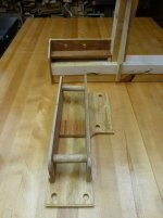
View attachment 419431
View attachment 419432

Photo 8 is a close up of the lower angle iron mount and the space for the c-clamp
to fit into. Note the verticle steel welded to the 2x2 upright as well as the 3x3 rail.
This may add strenght to the frame and rail design/torsion?
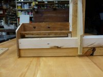
View attachment 419433

Well, there it is. Feel free to completely re-engineer.:thumbsup:
I like your full scale model. :thumbsup:

The wraparound c-clamp looks like it needs a longer wrap, the hole is too close to the edge. The bolt could tear out with a lot of weight on the tip of the fork.

Pallet Forks - Attach2.jpg


Make sure the fork frame will go low enough, his lift arm bolt/pin looks too low, unless your 3 point arms will touch the ground fully lowered.
 
   / Question about steel strength?? #168  
I like your full scale model. :thumbsup:

The wraparound c-clamp looks like it needs a longer wrap, the hole is too close to the edge. The bolt could tear out with a lot of weight on the tip of the fork.

View attachment 419555


Make sure the fork frame will go low enough, his lift arm bolt/pin looks too low, unless your 3 point arms will touch the ground fully lowered.
2D edge distance is a good rule of thumb. That is 2 times the hole diameter measured from the hole center to the edge of the material.
 
   / Question about steel strength?? #169  
"tonnage" is the operative word here.

Wonder how many tractor sub-forum projects use even a half ton of (purchased) new stock. Ptobably one post every 5 years,,,,

Or its not a tractor project at all just a guy talking about a bridge the county built,,,,

If not for A500 at the store there would be no tractor projects at all.
Tonnage made, not tonnage ordered.
With steel is is all about size.
The same number of men make 20 Tons with a 20 ton furnace in exactly the same time the same number of men can make 2000 tons in a 2000 ton furnace.
Naturally what comes out of the 2000 ton furnace will be cheaper.

Any 1/2 decient steel merchant will be able to order in any grade you require in compete lengths.
If you are doing a bit more work then , just like plain carbon steel it becomes cheaper if you buy a complete sling.
No one made wear plates ?
 
   / Question about steel strength??
  • Thread Starter
#170  
xfaxman and dragoneggs-

Thanks for the information.
Do you think the design for mounting the FEL brackets will work?

2D edge distance is a good rule of thumb. That is 2 times the hole diameter measured from the hole center to the edge of the material.
 

Tractor & Equipment Auctions

Round Bale Feeder with Skirt (A50515)
Round Bale Feeder...
JMR Tree Boom Skid Steer Attachment (A50322)
JMR Tree Boom Skid...
2016 Ford F-550 Palfinger PSC3216 Crane Service Truck (A51692)
2016 Ford F-550...
2022 New Holland Workmaster 120 MFWD Compact Utility Tractor (A52748)
2022 New Holland...
Yale Electric Pallet Jack (A50514)
Yale Electric...
2002 Wacker RD11A Tandem Smooth Drum Roller (A51691)
2002 Wacker RD11A...
 
Top