OP
woolyAcres
Platinum Member
That will out-lift any of these old yanamrs!Also I just got a great deal on a Backhoe Loader that will lift around 2500 lbs...
That will out-lift any of these old yanamrs!Also I just got a great deal on a Backhoe Loader that will lift around 2500 lbs...
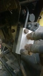
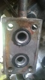
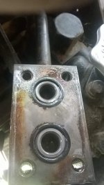
Not that I could find. There are dimples there but I tried (gently) to push a zip-tie through from one dimple to the other. It just folded up in my hand. That piece is mounted on the tractor so it's difficult to get a great view of it.I am slow. Are you saying there is not a straight through passage where the steel lines come in?
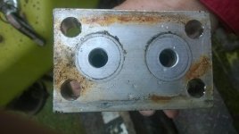
There was a different block which probably had a channel between the ports?I am a little puzzled. Before the loader lines were installed how did the flow go to the 3 point??? California, you got an answer???
There was a different block which probably had a channel between the ports?
Aaron Z