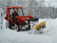
Bill here are some of the project pictures... Be kind, I'm not that great at welding.....But I've never had a weld break.
As you can see I cut the A frame arms right at the cylinder, leaving only enough as to not weaken the mount.


From there I attached the mounting plates to the top and made it so I could adjust the placement of the push plate if I ever needed to.
After that I sort of followed the same pattern you had in your 3D sketch, the big difference is the distance from the push plate to the plow.


I plowed with it today and I think I'm going to add some sort of shoes to the back edge of the frame. There seems to be a sweet spot for the cutting edge where it is able to run without digging in, but if you roll back too far on the front shoes your not able to cut the packed surface where vehicles have driven over the snow. I find myself having to adjust a lot on the fly. If I have rear runners or shoes that would simplify thing a lot. I'm also going to add a brace to the back of the plate to the connector arms just to improve the overall strength.
As for back dragging it works very well by just pitching forward with the push plate and the push plate makes contact with the A frame. The design seems solid, I can roll the push plate forward and add down pressure with the FEL and the plow and frame will hold the weight of the tractor with the front wheels suspended.
Over all I'm pleased with the performance and the design.
I want to thanks everyone for the help with the design and the feedback.