Help Interpreting Wiring Diagram & Using Multimeter

   / Help Interpreting Wiring Diagram & Using Multimeter #61  
First question and you may have answered it on the bench. When you power up the old and pull in winding it pulls in?
The leaving power on the holding and removing power from the pull in the shut off stays pulled in?
 
   / Help Interpreting Wiring Diagram & Using Multimeter
  • Thread Starter
#62  
Jumpers shown, x3, easy to make up, and allows testing and/or Jumpers while things are hooked up properly. Any auto parts store or hardware store would have the crimp on ends shown, take your solinoid with you to get the right size blade male/female ends. Install jumpers between factory connectors, make double sure you keep them going to the matching positions.

dieselcrawler, YES - VERY CLEVER !!! Great Idea, I will head off later this afternoon to HDepot with the Solenoid in-hand as you suggested, if no hit there then on to AutoZone or Advantage. I hate to say this, I'm in the middle of cutting (58) 103" lengths (alternating match) of wallpaper. If you hear someone swearing tomorrow (pulling from my old Navy Vocabulary) that will be me while hanging......... This is probably the 15th time since the 90s I've found myself papering, not the most enjoyable task but nice when it's done.......... Thanks Again, dieselcrawler...........
 
   / Help Interpreting Wiring Diagram & Using Multimeter #63  
Can you back probe the connector?
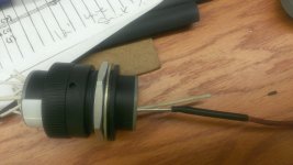
IMAG0023.jpg
This is using a Cat Spoon (7x-1710) it is dished and follows the wire to where you can touch the pin inside.
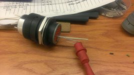
IMAG0024.jpg
chances are you don't have the fancy cat spoon. this is what i am talking about with paper clip like wire.
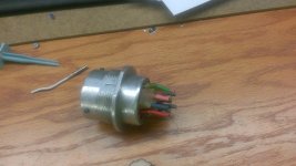
IMAG0025.jpg
Now if your plug looks like this you are not going to be able to back probe.
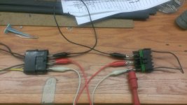
IMAG0026.jpg
I believe diesel crawler is talking about doing something like this.
Back probing will give you the best reading as the voltage drop could be in the plug.
If you can back probe,
One end of the meter goes to ground at the battery!, make sure you have good connection. back probe each wire and tell me what the readings are.
Next switch the ends of the meter, putting the end on the positive at the battery, tell me what readings are on all three wires.
before you are done I need battery voltage.
All readings are made with the solenoid engaged.
recap, when you are done you will have 7 readings.
3 connected to ground at the battery.
3 connect to positive at the battery.
battery voltage, all with solenoid engaged.
Now if you end up doing the last Picture. Which is the jumpers between the connectors, make sure you use an 18 awg wire. To small it will get hot and throw your readings off. In a nut shell you will make same readings as above. However, I would take the wire that you have going from the positive at the battery, once again making sure this wire is 18 awg at least. Disconnect the jumper going to the pull in winding, on the vehicle harness side and with the hold in powered up send 12 volts to the pull in. Based on what you have said above it should pull in as it sounds to me like you have a voltage drop on the pull inside of the coil wiring. Which is typical.
 
   / Help Interpreting Wiring Diagram & Using Multimeter #64  
Now that the solenoid is out and activated a few times have you connected it again and turned the key. This is with the solenoid out.
 
   / Help Interpreting Wiring Diagram & Using Multimeter #65  
My guess at this point is with the jumpers I showed earlier in place, and an additional jumper from the ground to another good ground, you will find it will operate properly.
 
   / Help Interpreting Wiring Diagram & Using Multimeter
  • Thread Starter
#66  
My guess at this point is with the jumpers I showed earlier in place, and an additional jumper from the ground to another good ground, you will find it will operate properly.

dieselcrawler, Got delayed with the Wallpaper prep, turned out to be (78) individual lengths and counting........so, didn't make it to HDepot but I found that I had an old kit of Terminals. For those down the line reading this thread, the terminals to make the jumpers (shown in the upper right corner of the attached PIC) are: Female Quick Disconnect 16-14 AWG Size 1/4" and Make Quick Disconnect, 16-14 AWG, size 1/4". I still have about 3 hours of Wallpaper chores to get done this morning then back to Testing. Understand (1) Additional Jumper for another Ground..........

Zebreafive, truckdiagnostics - Once I get the jumpers fabricated then I'll do the testing you suggest............truckdiagnostics, I've attached a PIC of the connector types used on the 790's Wiring Harness.

Egon, Before performing the Bence Testing with the Jumpers I'll reconnect Solenoid to the harness and place in the "Run" position to see if there's any change with the Selenoid's ability to do the plunger retraction.....Hoping this thread helps you find your issue.......

In the meantime until say noon'ish, back to the wonderful world of wallpapering prep......Tomorrow hanging starts, O What Fun.......
 

Attachments

  • IMG_6993.JPG
    IMG_6993.JPG
    1.9 MB · Views: 133
   / Help Interpreting Wiring Diagram & Using Multimeter #67  
The additional ground I'm referring to is basically a "T" in the ground jumper... allowing all factory wiring to be connected, but provide an additional good clean ground.

The key will need to be switched to the start position momentarily to retract the plunger, right? Or does it retract as soon as the key hits run position?
 
   / Help Interpreting Wiring Diagram & Using Multimeter
  • Thread Starter
#68  
The additional ground I'm referring to is basically a "T" in the ground jumper... allowing all factory wiring to be connected, but provide an additional good clean ground.

The key will need to be switched to the start position momentarily to retract the plunger, right? Or does it retract as soon as the key hits run position?

dieselcrawler,

I got some 14 AWG solid, but wondering that has that enough capacity for the jumper lines, if so, I got 6' each of BLK,GRN & RED, out of WHT color. You address a "Good Clean Ground", I know there's a Ground Wire going from the Battery & screwed to the Frame in the Battery area, not any rust but I hit it with some CRC 2-26 Dielectric Lubricant back some time ago. OK - The Additional Ground Wire coming off the "T" would go to another spot on the frame ?? Re: the Ignition Position: When I did the Zebrafive voltage checks the Pull-In voltage (for a second) was present at the "RUN" Position.

Egon,

Per your request before I get these Jumper Wires set-up, did a quick reconnect to the wiring harness, Ignition in "RUN" then "START" Not-ta, no movement of Plunger..........
 
   / Help Interpreting Wiring Diagram & Using Multimeter #69  
That would seem to indicate the problem may not be the solenoid. Shutdown switches , position switches, ??
 
   / Help Interpreting Wiring Diagram & Using Multimeter
  • Thread Starter
#70  
GOING OFF LINE FOR A COUPLE OF DAYS

ALERT ! Family visit coming-up this weekend, promised Little Lady aka Wife I'd get the Wallpapering finished before that visit, let's see......that was two months ago, boy time flies when you're having fun......not wallpapering.

dieselcrawler, Zebrafive I'll check back in Monday and hopefully with your assistance continue to solve this phantom problem. I'll build those Jumpers if the 14 AWG is sufficient for the 12V, if not, I'll get the right wire and larger terminals this weekend. Sorry for this delay, again, I appreciate your detailed guidance in this matter.
 

Tractor & Equipment Auctions

80in HD Tooth Bucket with Side Cutters ONE PER LOT (A51039)
80in HD Tooth...
2022 Case IH Steiger 470HD AFS Connect RowTrac 4WD Tractor (A50657)
2022 Case IH...
2019 New Holland Workmaster 95 MFWD Compact Utility Tractor with 632TL Loader - Poultry Special (A51039)
2019 New Holland...
2016 KBH Fertilizer Tender Trailer - Isuzu Diesel, Hydraulic System, Rear Discharge (A51039)
2016 KBH...
KSI Conveyor (A51039)
2018 CATERPILLAR 249D TRACKED SKID (A51222)
2018 CATERPILLAR...
 
Top