wmonroe
Elite Member
Wow good that you caught it before a heart attack. Good luck with the recovery!
Goodness, it is a year later, so guess I'm late to responding. Medical problems have made me set this aside for awhile (like open heart surgery!...but I'm doing good in recovery). My serial number puts it in the middle of 1962. We'll see... Bob
Stan,
You've done an amazing job on your Case 530CK. I have a 64 530CK, also with the Model 32 Backhoe. I am reportedly the 3rd owner of the piece of equipment as the last owner said he bought it from a city that had bought it new.
I bought mine to help in the building of a new house. It's not going to win any races or beauty contests, but it works pretty good.
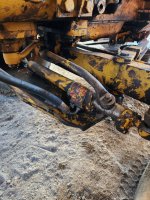
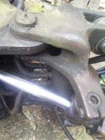
The biggest downside is that I just replaced one of the Swing Hoses and got about 8 hours of use before I blew one of the Bucket Hoses.
Somebody along the way has not been very kind to the Hard Lines and they're bent in places they weren't originally.
I guess this time while I have the Backhoe off, I'll double check all the hoses and replace all that are suspect.
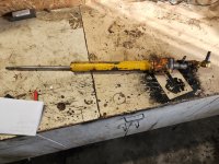
Do you have any advice for getting to the connections between the Bucket's Hose Connections to the Hard Lines at the base of the Lower Boom?
Thanks in advance!!
Dean
Stan,
Somebody along the way has not been very kind to the Hard Lines and they're bent in places they weren't originally.
I guess this time while I have the Backhoe off, I'll double check all the hoses and replace all that are suspect.
Do you have any advice for getting to the connections between the Bucket's Hose Connections to the Hard Lines at the base of the Lower Boom?
Thanks in advance!!
Dean


Stan,
In regards to my previous question, I hope I'm gaining ground. I can barely get wrenches on the fitting, but I have no room to turn them. I am expecting delivery on a set of Crow Foot Wrenches today, that I hope will work around my clearance issues.
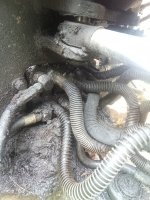
One other quick question if I may. All but one of the lines to the Backhoe Boom and subsequent cylinders appear to be 1/2", with the exception of what appears to be 3/4", to Boom Lower. This one Hose and Line is also the only one with the 3/4" JIC fittings and a larger line at the Backhoe Control Valve assembly.
I'm new to actually working on hydraulics and find it odd that only one line in a circuit would be larger than the other.
Do you have documentation calling out the size of the various lines and Hoses?
Again, your experience and willingness to help is greatly appreciated.
Thanks in Advance,
Dean


Hi mayorbob,
Glad to hear you're ok, I'm sorry about the medical problem and hope this is solid cure for the heart thing! A guy never knows what's around the corner, but it's also nice to find that you have found out more about your machine and that you are sharing it all with us here on the forum. I've got some more stuff that I've been doing for my 530; like building a fork lift for the loader arms. You take care of you and we'll be sharing more here, Stan.
Hey Stans,
Did you ever figure out the power steering? I picked up a 530ck Backhoe as well, and the wheel is almost impossible to turn. Certainly seems like something is binding up, and the power steering definitely isn't working.
I'm trying to find some issue on the single cylinder power steering system, and like you, can't find much info about it.
")


Stans,
Not sure how I got that mixed up! I guess I was in a hurry and it was late.
I believe mine is the early steering, with one cylinder on the axle. I checked the fluid level and it was empty. With fluid in the reservoir, the steering has gone from basically impossible to just having to really muscle the wheel. So a bit of an improvement for sure. I'm not sure if I need to bleed the system of air, and if so, how to do that, or if there's something else I'm missing.
The tie rod ends are shot, which I'm sure aren't helping anything. I'm generally pretty handy, but without seeing a diagram of the steering system i'm having a hard time figuring out what to look for next. They really managed to cover up all the systems on this tractor!

Hey Scotty,Nothing to add, just wanted to make sure this old thread is available in my personal list. It's fun to read.

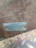
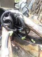
I was told by the previous owner that mine is a 63, but the identification plates are missing on the tractor and loader. The identification plate on the backhoe says it's a 31 model however instead of a 32. I have double piston steering. I also did find the engine serial number plate. I have pulled the hoses out of the boom arm (without unhooking anything) to show how much extra hose I am seeing.Hey, I'm going to be replacing some lines on the hoe of my 530CK and was wondering if you could help me out. I'll take pics when I can but there seems to be a LOT of extra line in the base of mine, and I was wondering if I should try and bypass the extra or just tie it up better than the last owner. Mine doesnt seem to have a pass through clamp but instead passthrough fittings in the hoe's base frame. Mine also has the outward facing swings.