3pt hitch Hydraulic top link and control

   / 3pt hitch Hydraulic top link and control
  • Thread Starter
#21  
That is weird. The three non-work ports should be Pressure, PB and tank. What do you think the rearward going hose do? Any chance you have any documentation on the tractor?

Where does the output of the 3rd function go?

Sorry "three non-work ports" referring to which valve? I have the FSM but only used it to confirm pump flow rate and what their "PB" port is.

By "output" of 3rd function you mean the "waste" (T) line or the two "work" line? The work lines go to the front bucket to open/close the jaw. The T line goes back to tank. That was originally from the FB control valve I previously called PB.

Aha moment? I found the FSM hydraulic schematic, and others folded at back of manual. Looks like of the two metal lines attached to the bucket (FL) valve to the rear, one come from the 3pt selector valve, the other goes to the BH (and from there back to 3pt selector). The FL valve shows 4 piston lines and one line to T, which is the one that now goes to 3rd function.

Having looked that over, schematically, it looks like I could tap in either at the 3rd function valve or at the 3pt hitch selector valve. Real world may make it a different story, space and access wise.

Hope that makes some sense/clear it up.
 
   / 3pt hitch Hydraulic top link and control #22  
I was talking about the FEL valve. Work ports are the things that go to functions. For the FEL, that would be curl and lift. The non-work ports would be whatever is left.

Having "tank" go to the 3rd function makes no sense. Tank "should be" under no pressure. It would be prudent to scan in the pertinent hydraulic diagram so we can see what you see.

I do not recall, are the BH and FEL OEM products or third party?
 
   / 3pt hitch Hydraulic top link and control
  • Thread Starter
#23  
I was talking about the FEL valve. Work ports are the things that go to functions. For the FEL, that would be curl and lift. The non-work ports would be whatever is left.

Having "tank" go to the 3rd function makes no sense. Tank "should be" under no pressure. It would be prudent to scan in the pertinent hydraulic diagram so we can see what you see.

I do not recall, are the BH and FEL OEM products or third party?

I may have the terms wrong. The diagram shows 7 connections, one being tank on the FLCV. I only counted 7 so assumed the one going to the 3rd function valve was PB. But, I guess that is wrong.

The FEL and BH are Kubota items TL421 and BT751. The bucket is a WR Long. I just noticed the WSM diagram is marked as B20, TL420, BT750, which may be an issue. Some of the diagrams in the back do show as for B21, TL421, BT751, but not all.

I also attached a routing diagram that may be useful.
 

Attachments

  • hyd1.pdf
    151.2 KB · Views: 65
  • hyd2.pdf
    179.4 KB · Views: 45
   / 3pt hitch Hydraulic top link and control #24  
You need get terms correct or it confuses those of us who can't see what you see.

You cannot run the 3rd function off tank. It has no flow unless a cylinder is in operation. So, we know that cannot be true.

You diagrams do not show your 3rd function. I wonder if is plumbed prior to the FEL valve. That might have been done if lines to the BH and 3pt are hard lines instead of hoses.

If I were you, I'd try to label all your lines and go from there. It would be messy, but I might unhook some lines, start the tractor for just a moment, and see which one spews fluid. That one is your supply line.

Also try this test. Slowly raise your FEL. While it's moving, activate your 3rd function. If it completely stops, your 3rd function is before the FEL. If not, its after.

Your hydraulic diagram is useful if accurate. Is shows your backhoe should work whether your 3pt is selected or not. That said, your backhoe loop would work to supply rear remotes. The only issue would be to figure out where to dump to tank.
 
   / 3pt hitch Hydraulic top link and control
  • Thread Starter
#25  
You need get terms correct or it confuses those of us who can't see what you see.

You cannot run the 3rd function off tank. It has no flow unless a cylinder is in operation. So, we know that cannot be true.

You diagrams do not show your 3rd function. I wonder if is plumbed prior to the FEL valve. That might have been done if lines to the BH and 3pt are hard lines instead of hoses.

If I were you, I'd try to label all your lines and go from there. It would be messy, but I might unhook some lines, start the tractor for just a moment, and see which one spews fluid. That one is your supply line.

Also try this test. Slowly raise your FEL. While it's moving, activate your 3rd function. If it completely stops, your 3rd function is before the FEL. If not, its after.

Your hydraulic diagram is useful if accurate. Is shows your backhoe should work whether your 3pt is selected or not. That said, your backhoe loop would work to supply rear remotes. The only issue would be to figure out where to dump to tank.

I appreciate your efforts and the confusion my terminology can cause.

The diagram is from Kubota, so it would not show the 3rd function. I did not try to draw in the 3rd function valve as I do really see, in the diagram, where it ties in. I did attach the valve specs and I believe the 2C diagram shows an unobstructed flow from what they call the P and T connections making it, in effect a PB in that configuration.

What I can say is that what comes out of the rear of the loader valve (Kubota may call this the "carry over pipe), which apparently is (was) the supply to the BH, does go to the P connection of the 3rd function. What is labeled T on the 3rd function goes to the BH.
20210610_094951 (Medium).jpg

Any way, I went to test as you suggested but did not get very far as one of the loader hoses sprung a leak. Nasty mess. Well, they are due for replacement anyway. I replaced all the BH hoses last year. At least these are easier to access.
 
   / 3pt hitch Hydraulic top link and control #26  
Ok then. Good. Loader is first. Then 3rd function, then BH. Typical. Now, figure out which of the two remaining lines on the loader valve is pressure and tank. You need to be able to tee into the tank line for the new rear remote valve.

Where the BH goes, I assume you have two lines you connect together when the backhoe is not in use. Correct? Your diagram seems to show that. This where you will insert your new rear remote valve.
 
   / 3pt hitch Hydraulic top link and control
  • Thread Starter
#27  
Ok then. Good. Loader is first. Then 3rd function, then BH. Typical. Now, figure out which of the two remaining lines on the loader valve is pressure and tank. You need to be able to tee into the tank line for the new rear remote valve.

Where the BH goes, I assume you have two lines you connect together when the backhoe is not in use. Correct? Your diagram seems to show that. This where you will insert your new rear remote valve.

The leaking hose has a bright side. While searching for part numbers, found the FEL list shows a "P.B. pipe" going from the back of the FEL valve to the BH area into a hose/quick coupler. Looks like that was replaced by 2 hoses (shown in earlier pictures), one going to the 3rd function valve and the other to the BH hose/coupler.

Looks like the other BH quick connect goes to the hitch implement control which has a tank connection, that appears to function as the tank return for the BH when connected and, I guess, the existing "T" (PB in this case) port of the existing 3rd function valve.

So, as long as the additional spool valve(s) I choose can "pass through" in "neutral" seems like I can tap into the PB circuit anywhere that is makes sense for ease of installation and use. I've only skimmed the info on the valves on Amazon and Ebay,
so do not know for sure such valves actually exists and how expensive they might be.

Make any sense?
 
   / 3pt hitch Hydraulic top link and control #28  
The leaking hose has a bright side. While searching for part numbers, found the FEL list shows a "P.B. pipe" going from the back of the FEL valve to the BH area into a hose/quick coupler. Looks like that was replaced by 2 hoses (shown in earlier pictures), one going to the 3rd function valve and the other to the BH hose/coupler.

Yet again, your sentence is confusing, please clarify. Do you have two hoses at PB or do you mean the PB port is routed to the 3rd function and then from the 3rd function to the backhoe. The first is a no-no. The second is normal.

Please share the FEL list if it is different than your previously posted pics.

Looks like the other BH quick connect goes to the hitch implement control which has a tank connection, that appears to function as the tank return for the BH when connected and, I guess, the existing "T" (PB in this case) port of the existing 3rd function valve.

Again, you imply that somehow you have hoses that go back to the 3rd function.

What does "goes to the hitch implement control which has a tank connection" mean? Given your hydraulic flow diagram previously posted. The output of the BH is still a PB line (most backhoes don't have a separate tank line for some reason). That PB line serves the 3PH as its pressure supply. It is not tank. The 3PH internally has its own tank port.

So, as long as the additional spool valve(s) I choose can "pass through" in "neutral" seems like I can tap into the PB circuit anywhere that is makes sense for ease of installation and use.
Yes, just disconnect the BH loop and install the valve there (logically). In practice, you have to find a place to mount the valve and get two short hoses with matching QDS to connect into the loop. You would connect the valve when using hydraulic implements and connect the BH when it is connected. There is no need to have the rear remotes active when the BH is attached (though you could do that too if you like). The important thing is that the hydraulic must always be serial and always be connected. Bad things happen when you don't.
I've only skimmed the info on the valves on Amazon and Ebay,
so do not know for sure such valves actually exists and how expensive they might be.

You need an open center valve. They are common. I'd recommend two or three ports. I have three. Haven't used the 3rd one yet. Its still plugged. But one day... :) Most valves can be configured closed center, open center or open center with PB. You want open center with PB. Normally you have to buy a "open center port" for a few dollars with the valve purchase. You also have to match the flow rate of the tractor. You want a valve that flows just a tad more than the tractor spec. Too big, and it won't feather well. Surplus Center is a good place to start looking for valves.

Look at this valve as an example. 3 Spool 8 GPM Prince MB31BBB5C1 DA Valve | Directional Control Valves | Hydraulic Valves | Hydraulics | www.surpluscenter.com

IT appears the power beyond plug is included, just needs to be installed.

Make any sense?
We are getting there. Still need to figure out how to do a tank line on the new valve.
 
   / 3pt hitch Hydraulic top link and control
  • Thread Starter
#29  
Yet again, your sentence is confusing, please clarify. Do you have two hoses at PB or do you mean the PB port is routed to the 3rd function and then from the 3rd function to the backhoe. The first is a no-no. The second is normal.
The FEL is the standard Kubota TL421. I was referring to the parts listing for that, which has a single "pipe" going to the BH connection.

The bucket is a WR Long with their 3rd function valve. The Kubota pipe was discarded, replaced by the 3rd function valve and two hoses, one a supply to the 3rd function valve, the other from there to the original BH conne\ction.

Please share the FEL list if it is different than your previously posted pics.
See above.

Again, you imply that somehow you have hoses that go back to the 3rd function.

See above

What does "goes to the hitch implement control which has a tank connection" mean? Given your hydraulic flow diagram previously posted. The output of the BH is still a PB line (most backhoes don't have a separate tank line for some reason). That PB line serves the 3PH as its pressure supply. It is not tank. The 3PH internally has its own tank port.

I meant the 3pt hitch. It is as you described.

Yes, just disconnect the BH loop and install the valve there (logically). In practice, you have to find a place to mount the valve and get two short hoses with matching QDS to connect into the loop. You would connect the valve when using hydraulic implements and connect the BH when it is connected. There is no need to have the rear remotes active when the BH is attached (though you could do that too if you like). The important thing is that the hydraulic must always be serial and always be connected. Bad things happen when you don't.

I had originally thought to do just that, get two more hoses and QD fittings to match the BH fitting, to plug them in when the BH is disconnected. Made sense to me. But then got to thinking too much and looking for easier/cheaper ways out and avoid extra QD and caps and attendant cleanliness issues.

You need an open center valve. They are common. I'd recommend two or three ports. I have three. Haven't used the 3rd one yet. Its still plugged. But one day... :) Most valves can be configured closed center, open center or open center with PB. You want open center with PB. Normally you have to buy a "open center port" for a few dollars with the valve purchase. You also have to match the flow rate of the tractor. You want a valve that flows just a tad more than the tractor spec. Too big, and it won't feather well. Surplus Center is a good place to start looking for valves.


You need an open center valve. They are common. I'd recommend two or three ports. I have three. Haven't used the 3rd one yet. Its still plugged. But one day... :) Most valves can be configured closed center, open center or open center with PB. You want open center with PB. Normally you have to buy a "open center port" for a few dollars with the valve purchase. You also have to match the flow rate of the tractor. You want a valve that flows just a tad more than the tractor spec. Too big, and it won't feather well. Surplus Center is a good place to start looking for valves.
Look at this valve as an example. 3 Spool 8 GPM Prince MB31BBB5C1 DA Valve | Directional Control Valves | Hydraulic Valves | Hydraulics | www.surpluscenter.com

IT appears the power beyond plug is included, just needs to be installed.
The tractor can do 8.3 GPM at pressure so I guess a 10 or 11 GPM valve is called for.

We are getting there. Still need to figure out how to do a tank line on the new valve.
This has me puzzled. Seems all the valves I've looked at state a tank connection needs to be hooked up, even with PB enabled. Puzzled because the BH, has spool valves (I presume) but no direct tank connection, relying on the 3pt hitch tank connection. Why is that OK, but not what we are talking about?

If I have to plumb in a tank line, in addition to "Pressure and PB", it would likely have to be "hard fittings" and I should just make the whole deal "hard plumbed".
 
   / 3pt hitch Hydraulic top link and control #30  
I had originally thought to do just that, get two more hoses and QD fittings to match the BH fitting, to plug them in when the BH is disconnected. Made sense to me. But then got to thinking too much and looking for easier/cheaper ways out and avoid extra QD and caps and attendant cleanliness issues.

You are thinking too much. :) This is the best solution and really, not much extra cash. The valve is the big ticket item and that won't change regardless of how you plumb it up.

The tractor can do 8.3 GPM at pressure so I guess a 10 or 11 GPM valve is called for.

That is reasonable.

This has me puzzled. Seems all the valves I've looked at state a tank connection needs to be hooked up, even with especially with PB enabled.

Go find some generic valve internal flow diagrams. You will see that on open center systems, you have a flow directly through all spools to the other end of the valve body and then you will have a "parallel" path on the exit side of each spool and they come together at the far end of the valve body. If this is the last (or only) valve in the system, that works fine. With power beyond, the main path (power beyond) and the exit path (tank) are separated. With that done, life is good for downstream valves.

Puzzled because the BH, has spool valves (I presume) but no direct tank connection, relying on the 3pt hitch tank connection. Why is that OK, but not what we are talking about?

You are only puzzled because you are right. Backhoes are plumbed stupidly. At least a lot of them. Certainly makes hooking up easier though not wondering where the tank line goes. I asked this question myself a few years ago and got no good answer.

I think I know now though. Consider above I described an open center valve where PB and tank were combined. It works because, being the last valve in a system, PB has nothing to do so PB and tank just flow together. Now, after the BH, there is the 3PH. The 3PH is also open center and fluid just flows through the middle if it is doing no work. Since it never does work with the backhoe attached, it is effectively just a pipe with blended tank and PB flow. Your new rear remotes will not have that scenario, so we need a tank line.

If I have to plumb in a tank line, in addition to "Pressure and PB", it would likely have to be "hard fittings" and I should just make the whole deal "hard plumbed".

I'd not do that unless you want to invest in tubing bending and flaring tools. Not fun without the right tools. I really want JIC flaring tools, but its just too much money.

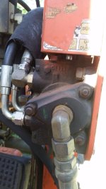
Post again your tank port picture on the tractor. We need to figure out how to get two lines teed in there. If I recall, it was a hard line with a banjo fitting. You can get banjo fittings on rubber hoses too. I'm thinking a short hose with a banjo on one end and a JIC on the other. A JIC tee. and then one rubber line aft and one back to the loader valve with whatever fitting is needed. I usually use a JIC on the hose and an adapter on the valve body if needed.
 
 
Top