Adding Hydraulic Side Links

   / Adding Hydraulic Side Links
  • Thread Starter
#31  
deerhunterf350 said:
I believe Jinman was referring to the Lift Arms Twisting , or rotating Left or Right as the Tilt was adjusted.

See attached Diagram


Condition A shows both cylinders set equally, the Implement is level


Condition B shows the most extreme Tilt you can achieve , and the Lift Arms tilt along with the Implement.
Aaahhh...I see what you mean. Thanks for the clarification. When I checked the movement for clearance I did not have the draw bar in the lift hooks which would cause the twist in the lower drag link. At this point I'm hoping Pat's EZ Change system allows enough movement...it did before but that was with slightly wider yokes. I am definitely going to have to check that out and report back.
Thanks,
 
   / Adding Hydraulic Side Links #32  
deerhunterf350 said:
I believe Jinman was referring to the Lift Arms Twisting , or rotating Left or Right as the Tilt was adjusted.

You might see some small amount of twisting as your diagram showed, but that is not the binding that caused my cylinder to break.

I was referring to the forward to aft tilt of the arms as my attached diagram shows. The point shown by the arrow is the most likely point for binding, or at least it was on my lift cylinder.
 

Attachments

  • yoke.jpg
    yoke.jpg
    8.8 KB · Views: 605
  • bustedtiltcylinder.jpg
    bustedtiltcylinder.jpg
    37 KB · Views: 617
   / Adding Hydraulic Side Links
  • Thread Starter
#33  
jinman said:
You might see some small amount of twisting as your diagram showed, but that is not the binding that caused my cylinder to break.

I was referring to the forward to aft tilt of the arms as my attached diagram shows. The point shown by the arrow is the most likely point for binding, or at least it was on my lift cylinder.
Hi Jim,
Sorry your cylinder yoke broke...good pictures.
I'm glad you clarified the previous post which I replied to. Your first photo/diagram depicts the "pinching" condition I thought you were talking about. As I said, I machined clearances for more room in the throat of the "U" and also machined 45° angles on both sides to allow free movement. That is what I tested for and no problem with that. You can see the 45° cut clearly on this picture.


On the other hand, I did not consider what deerhunter brought to attention. After thinking about it and studying an old picture of my box blade radically tilted, I did not notice as much twisting as he referred to. As a matter of fact, I was browsing the "Owning & Operating" discussion this morning and came across a post in a sideways mowing thread. It was by Golfgar4 and he posted a photo of his side arm mowing attachment. It showed the side links tilted way up and fastened to a draw bar...actually an EZ hitch. It shows clearly that the lower arms are not very twisted as much as deerhunter's diagram. I borrowed Golfgar4's photo to display here and you can see the lower lift arms almost straight.


Nevertheless, I am going to check that condition out myself when I go up to camp this weekend. It is still an area that might cause some binding or breakage if indeed, the lower drag links twist too much.
Thanks for the input...
 
   / Adding Hydraulic Side Links #34  
jinman said:
I was referring to the forward to aft tilt of the arms as my attached diagram shows. The point shown by the arrow is the most likely point for binding, or at least it was on my lift cylinder.
Hi Jinman!

Aside from the reason the weld was stressed to the breaking point...do you think that weld failed because it was a poor weld to begin with?

It sure looks like a cold MIG weld to me (I'm no expert by far, and the pictures are not that detailed either).

This is a side issue separate from the point you were making...just my first impression when I viewed you photo...:)
 
   / Adding Hydraulic Side Links #35  
It sure looks like a cold MIG weld to me (I'm no expert by far, and the pictures are not that detailed either).

Bill, I think you are right. The original Tisco cylinder did not have a very good weld. The one I got when I took the cylinder to have it welded is much better now I believe. I had them shorten the cylinder ram by 1-1/2" and drilled another hole lower down in the yoke. Otherwise, I would have had to grind the yokes like Rob did his. I sure think he has done a great job of thinking through all the "issues" with his cylinders. Just the fact that his Kama is so large has allowed him to do things that could not work on many of the smaller CUTs.
 
   / Adding Hydraulic Side Links
  • Thread Starter
#36  
Last weekend I got enough time to install the new 3 spool valve and plumb up all the hydraulics. Also in picking the path so they don't interfere with getting around the cab. There is a lot to making the hose connections come out the right length and using the right fitting connections.

Before going in to that, I had been asked to show the available tilt on the new cylinders. There was a question about the possibility of the drag links (lower arms) twisting from side to side and causing an interference with the cylinder yokes. I tilted them up and down to full extension and then stuck a 3/4" pipe through the hooks of Pat's EZ lift system. There was enough room but a little tight. However, I'll probably never have this drastic of a difference between the 2 cylinders? (maybe). If you look closely, you can see the raised arm on the left actually has some tilt to wards the right one, and visa-versa.


I also removed the quick disconnect bracket on the left side to give lots of room behind the tractor. If you look closely on the right of the photo, you can see where I ran the power beyond and return to sump along the inside of the right rear fender.
 
   / Adding Hydraulic Side Links
  • Thread Starter
#37  
I bought a Prince 3 spool open center valve with power beyond to control the new rear remotes. I now have 3 sets of rear remotes with this valve. Remember that the existing 2 spool valve (was for my rear remotes) now controls the hydraulic tilt cylinders individually. The valve is very big and I had to pick the right place to mount it so the control levers were within easy reach when I was looking back wards. I also mounted the levers facing inwards so they are really easy to get at.

I ended up installing it into a tool box I made and mounted on the right fender. I cut the box to fit the entering and exiting hoses and made a steel bracket to support it. It looks a little busy but it is completely out of the way. I managed to route 6 hoses between the ROPS and the tool box. The power in, power beyond and return to sump all follow the ROPS down to the floor board. I used 4000 psi hose bought from Agri-Supply. Not too bad for having nine ½" hoses altogether.

Here is a view from the front like from the steering wheel, showing a corner of the the drivers seat on the right.


This view shows it from the rear ward position, showing a corner of the driver's seat on the left. I can still keep 2 grab chains and some tools in the rest of that tool box.

 
   / Adding Hydraulic Side Links
  • Thread Starter
#38  
This is a view from the rear of the tractor to show where the rear remotes are now located. I put them higher up on the back of the right rear fender. Look how easy they are to get now, compared to the old location which was blocked off when you had an implement mounted. The new location is much more user friendly and all my attachment hoses still reach to the new location. The rest of the cylinder plumbing also looks good.

 
   / Adding Hydraulic Side Links #39  
Looks fantastic ! But i'd expect no less. I'll be content when i do my remote install if it comes out half as professional looking. Just curious...... do you have a crimper to make your own hydraulic hoses? Or did you actually measure, then order them over the phone and have them the correct length the first time? I've had hoses made in the $90 range (obviously much longer)... so it wouldn't take much mismeasuring to waste alot of money.

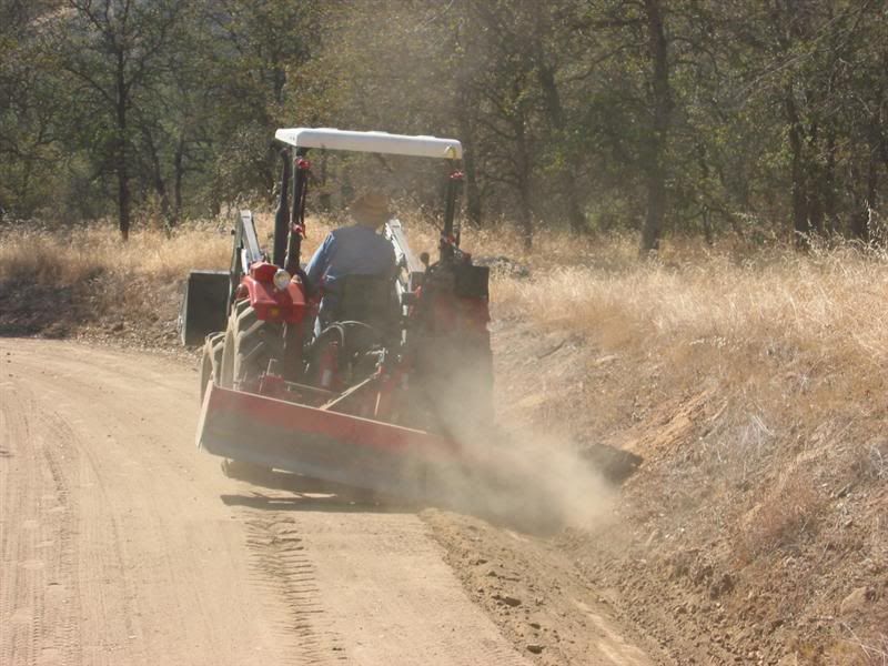
Nice work Rob ! Now we need some action pictures.
 
   / Adding Hydraulic Side Links
  • Thread Starter
#40  
These last couple photos are close-ups. This one shows the 3 new sets of remotes on the Kama.


And finally, after checking everything for leaks (one fitting I forgot to tighten) I had Loretta take a shot of the new pressure gauge showing the system at 2300 psi when under full load. That's where my valve's reliefs are set for safety. My main hydraulic system is rated to operate just under 2500 psi.


It was great to see how the pressure ran up when using the loader and other implements and then spiked up to the relief valve pressure under full load. I was really surprised how little pressure the loader, 3pt and other cylinders handled most loads, only spiking when I maxed out at the end of the travel. Now I can keep tabs on how the hydraulic system is working and whether it starts to show excess pressure due to a dirty strainer or blockage, or when there is no pressure and a possible leak.

I hope this project may have helped someone who is considering hydraulic additions. There might be improvements whereby you can improve your installation....learn from my mistakes? My recommendation is to use either JIC fittings or SAE fittings where possible. They are very leak proof and run up to a positive stop and an "O" ring. The NPT fittings are more difficult and require pipe dope to get a good seal. In my case, there were several places I had to go from Metric 22mm x 1.5mm pitch (not BSP) to American. This made for an interesting collection of fittings I needed.

I've tried to show what is involved and that even a hack like me can make the installation with success. Everything works and I am very happy with the results.
Thanks,
 

Tractor & Equipment Auctions

TC710 FINISHING MOWER (A50459)
TC710 FINISHING...
2017 Makita HM1307CB 35lb Demolition Hammer (A49461)
2017 Makita...
2008 Ford F-250 Knapheide Service Truck (A50323)
2008 Ford F-250...
2021 CATERPILLAR 259D3 SKID STEER (A51242)
2021 CATERPILLAR...
2022 Case IH Steiger 470HD AFS Connect Quadtrac 4WD Tractor, (A50657)
2022 Case IH...
1041 (A50459)
1041 (A50459)
 
Top