Adding Hydraulic Side Links

   / Adding Hydraulic Side Links
  • Thread Starter
#21  
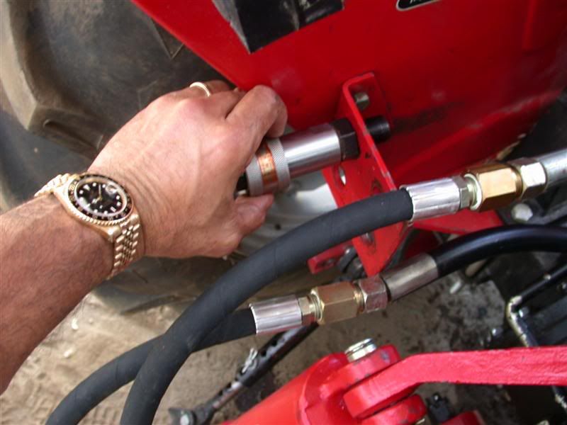
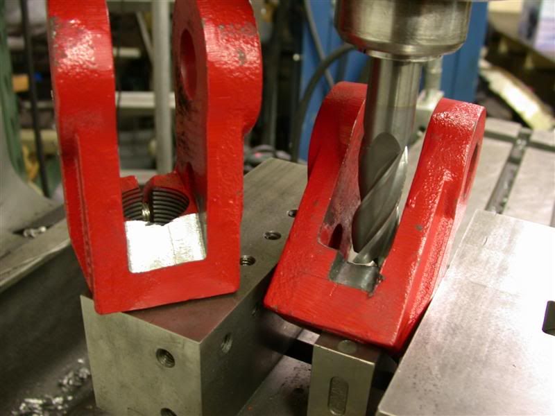
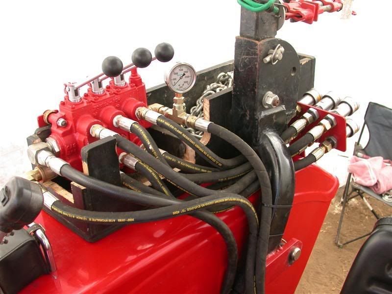
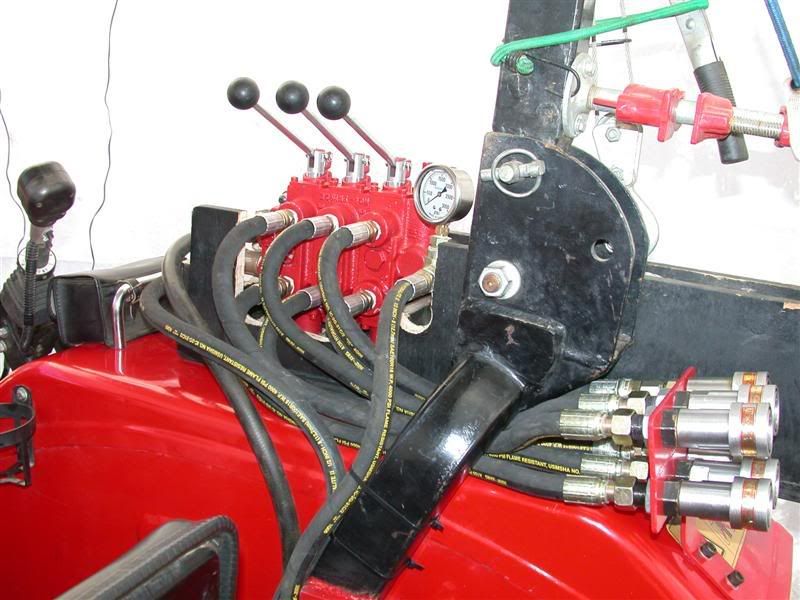
I needed them because I was not sure how it was going to turn out. Especially mounting...hard plumbing the double pilot operated check valves I bought from Surplus Center. I had machined some various nipple lengths in order to get the spacing correct for the hard plumbing. After trying it several times, I finally got the right combination and made a good plumbing job of it. I used pipe joint compound for the NPT fittings. The others were SAE and JIC fittings.

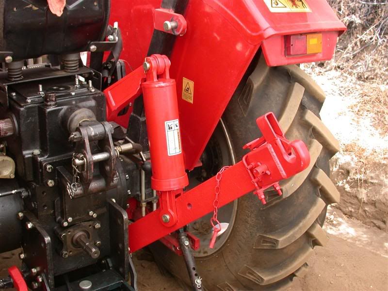
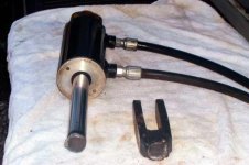
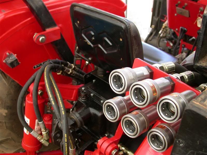
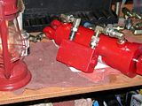
Here's what the cylinder looks like with the check valve mounted. It was a lot harder than I thought but came out just fine. One thing for sure, the Surplus Center DPOCV is a lot bigger than the CCM one on my top link cylinder.


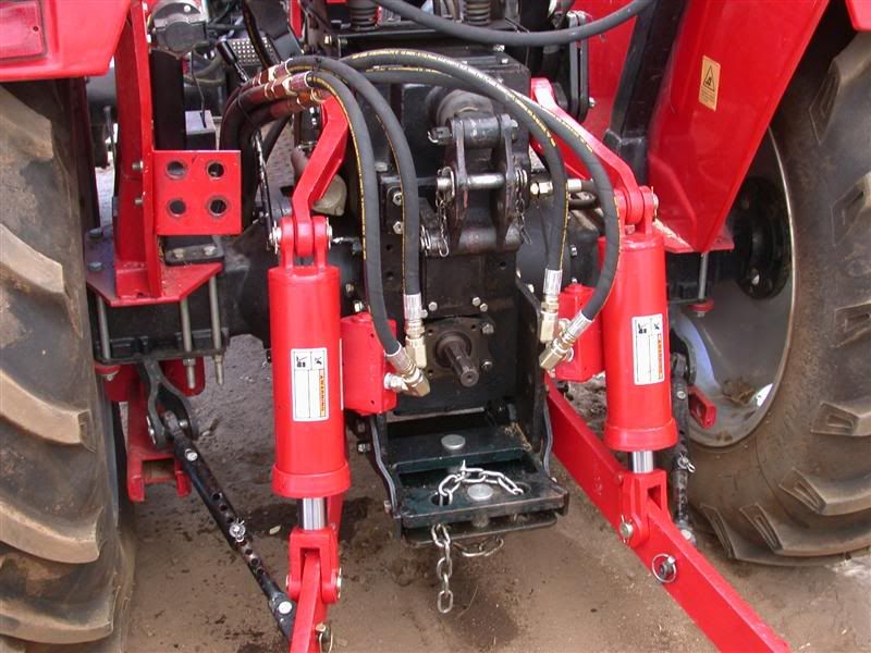
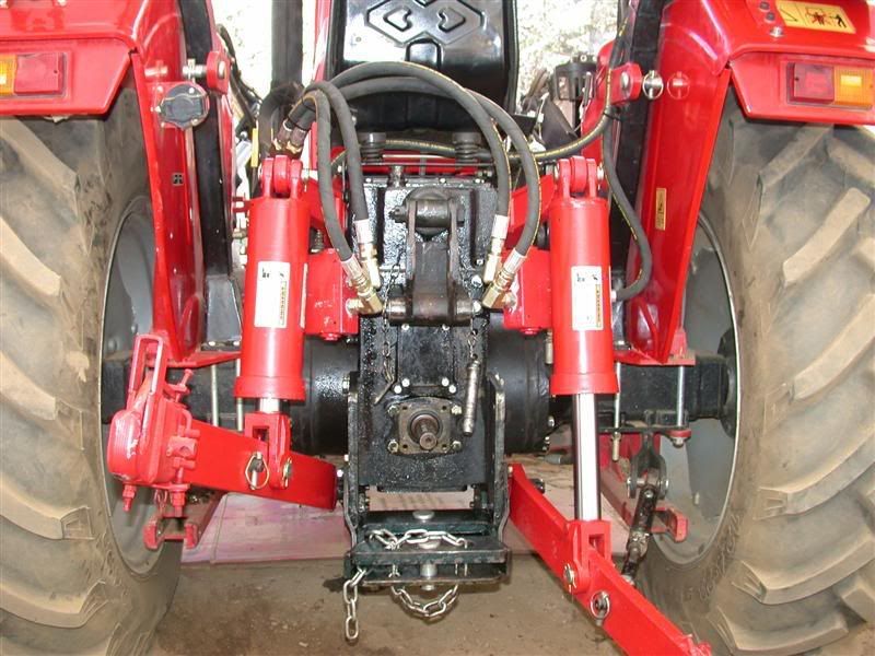
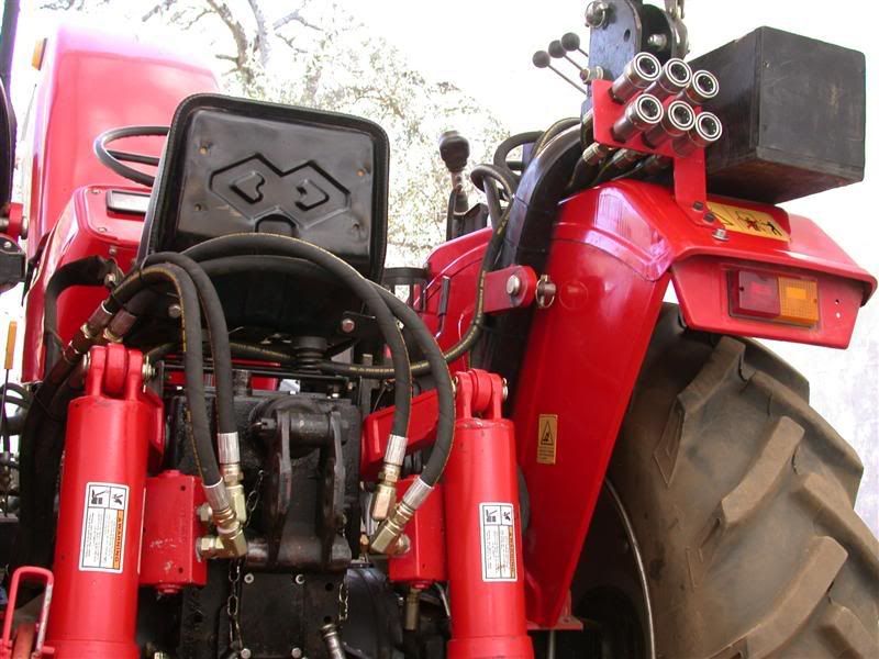
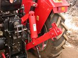
Then I took the cylinder assembly and mounted it to the tractor. I had previously re-attached the top lift arms and lower drag links to be certain I had them in the correct position. The top lift arms are splined so you can set on the tractor at different positions. So I had to check the full movement of the arms to see if there would be any binding or interference. I also checked the to see where the full length and shortened length of the cylinder would position the lower drag arms.

Anyway, this is how the cylinder looks when in position.

 
   / Adding Hydraulic Side Links
  • Thread Starter
#22  
When considering how to plumb the tractor, I had decided earlier on that I would use the new 3 spool valve to control the top link and also the hydraulic rippers on my box blade. It will also give me one more set of remotes for whatever else I come up with? That meant making a new Quick dis-connect bracket and having all the hoses go there. Unfortunately, I didn't have time to install the new valve. We were planning on dove hunting and also going up to Sequoia to see the giant Redwoods. Another thing I had to do was trench some deep holes for the solar guy. They are for the solar trackers and had to be 4' x 4' x 5' deep!!.

So I hooked up the new side cylinders to the old valve that ran the rear remotes. In fact, it made good sense since it's levers were next to each other, left and right. So it was easy to tell which lever runs which. That way the 3pt system was in tact and ready to use. I also got some metric adapters (22mm x 1.5 pitch) to make the connections to the Chinese threads.


After getting everything screwed together and trying them out, I had to be certain none of the hose interfered with the 3pt system and that they had enough room and play regardless of what I hooked up...including the PTO pump for the backhoe.

So this is what that turned out like. No leaks and everything fits, works and is tucked away nicely. To my surprise, even the big check valves look decent.


Right after that, I hooked up the backhoe and dug those big holes. Next time up I'll tackle the 3 spool valve installation.
 
   / Adding Hydraulic Side Links #23  
Rob,
Good looking job. One point that I would like to make though is for you to keep an eye on the check valves the first time or two that you use your bush mower. The check valves might get into the PTO shaft as the mower moves around.
 
   / Adding Hydraulic Side Links #24  
Nice Job Rob. You are one prolific tractor customizer! All you need is a producer and you'll be starring in Tractor Shop on Discovery.

It looks like despite the bulk of your tilt cylinders you actually eliminated an interference problem. On mine the D-handles on the left side link can interfere with the remote quick-connects.
My tractor came with a set of 4 matching male quick-connects for the remotes. I guess either yours did not or more of them are not readily available for use on other implements.
 
   / Adding Hydraulic Side Links #25  
Brad_Blazer said:
Nice Job Rob. You are one prolific tractor customizer! All you need is a producer and you'll be starring in Tractor Shop on Discovery.
He has the most modified Kama in North America.:D
 
   / Adding Hydraulic Side Links
  • Thread Starter
#26  
Well, I sure am glad it turned out and also that you guys like the conversion. I have a tremendous amount of tilt available with the 2 cylinders. It became a small PITA trying to turn those turnbukles with the box blade under tension with a full load in it.

And you're right Brad, no interference with the QD's on the left side any more. I've smashed my knuckles many times adjusting that one. I took them out and will re-mount them on the right rear fender on a new bracket next time I go up. They will not interfere with anything there and be more easily reached for the attaching/disconnecting. Mine came with 4 females in the bracket and males for my implements. I have since purchased 4 more (8 total males now) and metric/SAE conversion fittings for all my implements. In any case, the new cylinders clear everything nicely in it's complete range of motion. (Where are the TV cameras when you need them?)

Jerry, thanks for warning about the check valves. I tried to take all implement mounting into consideration but I'll be sure to position the mower at extremes before I kick in the PTO and then keep an eye on the shaft. Also, thanks for the kind words and encouragement you have given me on all my projects. I'll post more on the valve installation next week.
 
   / Adding Hydraulic Side Links #27  
Rob, you've done a very nice job with your tilt cylinders. The big DPOCVs look a lot less bulky on your Kama than I thought they would. How about control? can you feather the cylinders or are they pretty fast when you move them? Did you put orifices in the lines? Will you be adding a toplink cylinder next?

On my sidelink, I didn't leave enough space in the yoke on the bottom to clear the lift arm at all angles (raised and lowered). As a result, I broke the yoke off the end of the ram when my subsoiler dug in and went too deep. You yokes look close tolerance. I'd check to make sure they clear. You might have to modify the lift arms slightly like you did the upper links to clear the cylinder.
 
   / Adding Hydraulic Side Links
  • Thread Starter
#28  
Hi Jim,
Yeah, those cylinders are 3-½" diameter and are pretty big themselves. So the check valves are not as big looking next to them....but believe me, they are really big! I wanted to get cylinders with at least a 1-½" diameter rod to avoid bending them when bulldozing in reverse with the box blade. These came with 1-3/4" rods so it's definitely heavy duty. I had already bent one of the stock turnbuckles (Ø1" threaded rod).

I didn't need to restrict the lines at all since the cylinders are so big it allows for slow-controlled movement and feathering even with the check valves is very easy. They warned against "chattering" when the check valves are used and I noticed a slight amount at first but after the cylinders purged now they are a lot smoother.

I already have the CCM hydraulic top link with check valve and they could not send me the side link kit since last October...nearly a year ago. That's why I did this myself. I also wish the CCM top link I bought was a heavier cylinder. Some implements are Cat II and it strains. I'll probably switch it to a larger cylinder before long and use their check valve for it.

As far as clearance between the lower drag links and cylinder yoke, I was able to machine 45° angles and reduce the amount of engagement by nearly and inch, giving me the desired tilt angles and clearances (yoke vs arms). I checked for this on both the lower and upper arms so I wouldn't screw myself when I got up to the property and sit there with my thumb up my you know what....hahaha Also, the upper and lower lift arms are pretty much inline so when raised or lowered their relationship stays constant...no angling off sideways.
 
   / Adding Hydraulic Side Links
  • Thread Starter
#29  
I would highly recommend this mod to your tractor if not done so already along with the hydraulic top link. The capability to equalize, tilt, adjust easily is so much useful in many applications. It's all done with a great viewpoint from the tractor seat. The best part is grading for example, you can drag your box blade with infinite settings WHILE MOVING and instantly see the result of the grade of cut you are making.

There have been many, many times I've had to stop the tractor, park brake (maybe turn engine off), get off and adjust the turnbuckles on the side and top links. Then climb back on (maybe start) park brake off, put back in gear and drive ONLY to find that my adjustment was not adequate...then do it over again until I got the right setting to produce the desired finish or grade. Of course, that changes after moving forward a bit and guess what? So now this whole thing is done from the operators seat and adjustable for varying conditions.

Once I get the road smoothed constant, crowned and guttered the way I want, the check valves will earn their keep.

The cylinders I chose were expensive and I bought a lot of fittings. The hose from Agri Supply were 1/2" and relatively inexpensive. I ordered everything on line after getting the right lengths and figuring out what connections I needed. The check valves were expensive too, but worth it for me. The way I did it and the cylinder size/quality I chose ... it cost me around $650.

I figure if a guy wanted to do this project he could get smaller cylinders and less expensive ones...they will all work as long as they fit and allow enough clearance in the system. Without the check valves you can do it for about $400 including a 2 spool lever valve. This is for 2 cylinders...if you use one it is even less expensive by the reduced cost of the valve, cylinder, fittings and hoses.

Another way to consider doing it is to use your rear remotes as the power supply with quick disconnects to the cylinder(s) AND a check valve. Theoretically, a guy could use the QD's to set the desired tilt etc. and remove the QD's to run another implement. The check valve should hold the cylinder in that position until you move it. If you use only one cylinder and you have 2 rear remotes, you could leave it hooked up all the time and maybe not even need the check valve? then you can do it for the cost of 1 cylinder, fittings and 2 hoses...no spool or check valve.
Rob-
 
   / Adding Hydraulic Side Links #30  
I believe Jinman was referring to the Lift Arms Twisting , or rotating Left or Right as the Tilt was adjusted.

See attached Diagram


Condition A shows both cylinders set equally, the Implement is level


Condition B shows the most extreme Tilt you can achieve , and the Lift Arms tilt along with the Implement.
 

Attachments

  • liftarm.jpg
    liftarm.jpg
    63.4 KB · Views: 908
   / Adding Hydraulic Side Links
  • Thread Starter
#31  
deerhunterf350 said:
I believe Jinman was referring to the Lift Arms Twisting , or rotating Left or Right as the Tilt was adjusted.

See attached Diagram


Condition A shows both cylinders set equally, the Implement is level


Condition B shows the most extreme Tilt you can achieve , and the Lift Arms tilt along with the Implement.
Aaahhh...I see what you mean. Thanks for the clarification. When I checked the movement for clearance I did not have the draw bar in the lift hooks which would cause the twist in the lower drag link. At this point I'm hoping Pat's EZ Change system allows enough movement...it did before but that was with slightly wider yokes. I am definitely going to have to check that out and report back.
Thanks,
 
   / Adding Hydraulic Side Links #32  
deerhunterf350 said:
I believe Jinman was referring to the Lift Arms Twisting , or rotating Left or Right as the Tilt was adjusted.

You might see some small amount of twisting as your diagram showed, but that is not the binding that caused my cylinder to break.

I was referring to the forward to aft tilt of the arms as my attached diagram shows. The point shown by the arrow is the most likely point for binding, or at least it was on my lift cylinder.
 

Attachments

  • yoke.jpg
    yoke.jpg
    8.8 KB · Views: 623
  • bustedtiltcylinder.jpg
    bustedtiltcylinder.jpg
    37 KB · Views: 637
   / Adding Hydraulic Side Links
  • Thread Starter
#33  
jinman said:
You might see some small amount of twisting as your diagram showed, but that is not the binding that caused my cylinder to break.

I was referring to the forward to aft tilt of the arms as my attached diagram shows. The point shown by the arrow is the most likely point for binding, or at least it was on my lift cylinder.
Hi Jim,
Sorry your cylinder yoke broke...good pictures.
I'm glad you clarified the previous post which I replied to. Your first photo/diagram depicts the "pinching" condition I thought you were talking about. As I said, I machined clearances for more room in the throat of the "U" and also machined 45° angles on both sides to allow free movement. That is what I tested for and no problem with that. You can see the 45° cut clearly on this picture.


On the other hand, I did not consider what deerhunter brought to attention. After thinking about it and studying an old picture of my box blade radically tilted, I did not notice as much twisting as he referred to. As a matter of fact, I was browsing the "Owning & Operating" discussion this morning and came across a post in a sideways mowing thread. It was by Golfgar4 and he posted a photo of his side arm mowing attachment. It showed the side links tilted way up and fastened to a draw bar...actually an EZ hitch. It shows clearly that the lower arms are not very twisted as much as deerhunter's diagram. I borrowed Golfgar4's photo to display here and you can see the lower lift arms almost straight.


Nevertheless, I am going to check that condition out myself when I go up to camp this weekend. It is still an area that might cause some binding or breakage if indeed, the lower drag links twist too much.
Thanks for the input...
 
   / Adding Hydraulic Side Links #34  
jinman said:
I was referring to the forward to aft tilt of the arms as my attached diagram shows. The point shown by the arrow is the most likely point for binding, or at least it was on my lift cylinder.
Hi Jinman!

Aside from the reason the weld was stressed to the breaking point...do you think that weld failed because it was a poor weld to begin with?

It sure looks like a cold MIG weld to me (I'm no expert by far, and the pictures are not that detailed either).

This is a side issue separate from the point you were making...just my first impression when I viewed you photo...:)
 
   / Adding Hydraulic Side Links #35  
It sure looks like a cold MIG weld to me (I'm no expert by far, and the pictures are not that detailed either).

Bill, I think you are right. The original Tisco cylinder did not have a very good weld. The one I got when I took the cylinder to have it welded is much better now I believe. I had them shorten the cylinder ram by 1-1/2" and drilled another hole lower down in the yoke. Otherwise, I would have had to grind the yokes like Rob did his. I sure think he has done a great job of thinking through all the "issues" with his cylinders. Just the fact that his Kama is so large has allowed him to do things that could not work on many of the smaller CUTs.
 
   / Adding Hydraulic Side Links
  • Thread Starter
#36  
Last weekend I got enough time to install the new 3 spool valve and plumb up all the hydraulics. Also in picking the path so they don't interfere with getting around the cab. There is a lot to making the hose connections come out the right length and using the right fitting connections.

Before going in to that, I had been asked to show the available tilt on the new cylinders. There was a question about the possibility of the drag links (lower arms) twisting from side to side and causing an interference with the cylinder yokes. I tilted them up and down to full extension and then stuck a 3/4" pipe through the hooks of Pat's EZ lift system. There was enough room but a little tight. However, I'll probably never have this drastic of a difference between the 2 cylinders? (maybe). If you look closely, you can see the raised arm on the left actually has some tilt to wards the right one, and visa-versa.


I also removed the quick disconnect bracket on the left side to give lots of room behind the tractor. If you look closely on the right of the photo, you can see where I ran the power beyond and return to sump along the inside of the right rear fender.
 
   / Adding Hydraulic Side Links
  • Thread Starter
#37  
I bought a Prince 3 spool open center valve with power beyond to control the new rear remotes. I now have 3 sets of rear remotes with this valve. Remember that the existing 2 spool valve (was for my rear remotes) now controls the hydraulic tilt cylinders individually. The valve is very big and I had to pick the right place to mount it so the control levers were within easy reach when I was looking back wards. I also mounted the levers facing inwards so they are really easy to get at.

I ended up installing it into a tool box I made and mounted on the right fender. I cut the box to fit the entering and exiting hoses and made a steel bracket to support it. It looks a little busy but it is completely out of the way. I managed to route 6 hoses between the ROPS and the tool box. The power in, power beyond and return to sump all follow the ROPS down to the floor board. I used 4000 psi hose bought from Agri-Supply. Not too bad for having nine ½" hoses altogether.

Here is a view from the front like from the steering wheel, showing a corner of the the drivers seat on the right.


This view shows it from the rear ward position, showing a corner of the driver's seat on the left. I can still keep 2 grab chains and some tools in the rest of that tool box.

 
   / Adding Hydraulic Side Links
  • Thread Starter
#38  
This is a view from the rear of the tractor to show where the rear remotes are now located. I put them higher up on the back of the right rear fender. Look how easy they are to get now, compared to the old location which was blocked off when you had an implement mounted. The new location is much more user friendly and all my attachment hoses still reach to the new location. The rest of the cylinder plumbing also looks good.

 
   / Adding Hydraulic Side Links #39  
Looks fantastic ! But i'd expect no less. I'll be content when i do my remote install if it comes out half as professional looking. Just curious...... do you have a crimper to make your own hydraulic hoses? Or did you actually measure, then order them over the phone and have them the correct length the first time? I've had hoses made in the $90 range (obviously much longer)... so it wouldn't take much mismeasuring to waste alot of money.

Nice work Rob ! Now we need some action pictures.
 
   / Adding Hydraulic Side Links
  • Thread Starter
#40  
These last couple photos are close-ups. This one shows the 3 new sets of remotes on the Kama.


And finally, after checking everything for leaks (one fitting I forgot to tighten) I had Loretta take a shot of the new pressure gauge showing the system at 2300 psi when under full load. That's where my valve's reliefs are set for safety. My main hydraulic system is rated to operate just under 2500 psi.


It was great to see how the pressure ran up when using the loader and other implements and then spiked up to the relief valve pressure under full load. I was really surprised how little pressure the loader, 3pt and other cylinders handled most loads, only spiking when I maxed out at the end of the travel. Now I can keep tabs on how the hydraulic system is working and whether it starts to show excess pressure due to a dirty strainer or blockage, or when there is no pressure and a possible leak.

I hope this project may have helped someone who is considering hydraulic additions. There might be improvements whereby you can improve your installation....learn from my mistakes? My recommendation is to use either JIC fittings or SAE fittings where possible. They are very leak proof and run up to a positive stop and an "O" ring. The NPT fittings are more difficult and require pipe dope to get a good seal. In my case, there were several places I had to go from Metric 22mm x 1.5mm pitch (not BSP) to American. This made for an interesting collection of fittings I needed.

I've tried to show what is involved and that even a hack like me can make the installation with success. Everything works and I am very happy with the results.
Thanks,
 

Tractor & Equipment Auctions

2953CFL (A59228)
2953CFL (A59228)
2019 Dodge Durango AWD SUV (A59231)
2019 Dodge Durango...
HYDRAULIC THUMB CLAMP FOR MINI EXCAVATOR (A58214)
HYDRAULIC THUMB...
2007 FORD F-150 XL TRITON (A58214)
2007 FORD F-150 XL...
2018 Deere 323E (A53317)
2018 Deere 323E...
2017 Kia Soul SUV (A59231)
2017 Kia Soul SUV...
 
Top