bending 4x4x.250 sqtube

/ bending 4x4x.250 sqtube #61  
JB, I think that 24,000 lb rated hub might be "right in the hunt" for this project. Plus it's built to take a cyclic load for tens of thousands of miles, with a significant safety factor (DOT approval).

This log loader's gonna cook Mudd out of his house before it even scrounged a hundred 2000 lb logs at 16ft extension, I don't see the cycles adding up to anything significant.

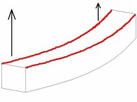
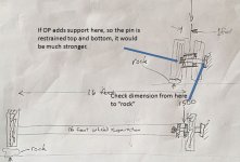
Truck hub widened to 16 feet and runs over a rock, lifting inside tire off the ground. 1500 lbs at 16 feet creates the same moment on the axle stub as 24,000 lbs on just one wheel. 1500 x 16ft = 24,000 x 1ft

The FBD is not really correct, it's a simplification. The load actually comes in where the hub is affixed thus it can support MORE than 1500 lbs at 16 feet. This is just to make the point is I think that hub is OK. Can you look at my assumptions and give your opinion?

424622d1431463587-bending-4x4x-250-sqtube-16foot_hub-jpg
 

Attachments

  • 16foot_hub.jpg
    16foot_hub.jpg
    123.4 KB · Views: 384
Last edited:
/ bending 4x4x.250 sqtube #62  
JB, I think that 24,000 lb rated hub might be "right in the hunt" for this project. Plus it's built to take a cyclic load for tens of thousands of miles, with a significant safety factor (DOT approval).

This log loader's gonna cook Mudd out of his house before it even scrounged a hundred 2000 lb logs at 16ft extension, I don't see the cycles adding up to anything significant.

Can you look at my assumption here and give your opinion if it applies? Truck hub widened to 16 feet and runs over a rock, lifting inside tire off the ground. 1500 lbs creates the same moment on the axle stub as 24,000 lbs on just one wheel.

424622d1431463587-bending-4x4x-250-sqtube-16foot_hub-jpg

The drawing looks mostly correct. One minor correction in attached image. However, I'm not sure the assumptions are accurate. I'm not positive on the construction of all truck axles, but from what I've seen, the tire is often directly over the bearing, not a foot out like you have drawn. Also with dual tires, it takes quite a bit to get the 2nd (inner tire) completely unloaded like you have shown.

Regardless, the addition of a second support would make it much stronger, and remove the hub from a significant bending load.

My original concerns still exist however, that this kind of a design and build takes some engineering effort, especially to make it safe. An understanding of moments and resulting forces are critical to a safe design. This is not a log splitter build, and a failure due to something not considered could have serious consequences.
 

Attachments

  • ScreenHunter_81 May. 12 17.09.jpg
    ScreenHunter_81 May. 12 17.09.jpg
    101.7 KB · Views: 172
/ bending 4x4x.250 sqtube #64  
I thought about the 4x6, but what I am running into is not having enough base metal to make the base mount. Right now as I have it drawn out, the boom mount is in the center on above my hub. The base pin for the cylinder is just inside the outer edge of the 20in wide base. I can slide the side mounts forward and mount the boom off center of the hub, probably wouldnt have to move it more than about a inch, but the more I move it off center, the more side load I place on the hub. Ideally, the boom would be mounted back of center and the cyl mounted forward of center to even out the load, I think?? I could always look for more metal to make the base out of, but used flat plate around here is hard to come by and expensive to buy new. Just going from 4x4 to 5x5 moved my top boom mount up almost 2 inches. I would have thought only 1/2in, the difference between the center of tube to outer edge, but it didnt work out that way. I havent said this yet, but the hub extends 6 inches up and is 8.5 inches wide in between the upright side mounts. Just doesnt give me a lot to play with. I'll take a pic of the setup to show what I mean.

Dont know if you can tell what the first pic is, its where I drew everything out on the garage floor. Piss on Autocad.

Mudd can you make some measurements on your spindle for the hub? I can run a quick calculation that would take many of the assumptions out of the equation.

Also I am not trying to rain on your parade whatsoever. I just know there are things that I have built that have failed in ways I had not considered until it happened. It's tough to consider all the resulting forces etc. I can try to help as I'm able to moving forward as you get dimensions worked out.
 
/ bending 4x4x.250 sqtube #65  
Another way is to build the thing, crank all the relief valves down tight, slowly proof it on 3,000 lbs. Watching it carefully, how & where it flexes, maybe measure it and come back to the forum. Then dial the relief valves back to 2,000 lbs and you have sort of a 1.5 safety factor (for some conditions). That doesn't proof it for off-axis, dynamic loads, stabilizers sinking, etc,,, but maybe you can think of ways to get confidence there too.

4x6 is a good way to prevent a truss, but I don't see the reason, especially if it adds weight and causes trouble too.
 
/ bending 4x4x.250 sqtube #66  
4x6 is no heavier than 5x5, but alot stronger in the direction he needs it
 
/ bending 4x4x.250 sqtube #67  
4x6 is no heavier than 5x5, but alot stronger in the direction he needs it

You were going to add " and in the direction that a truss could solve more elegantly with less cost and less weight." ????

Sorry ( not paid by the truss lobby, honest! :D )
 
/ bending 4x4x.250 sqtube #68  
One good thing about trusses, they are fun to build. :thumbsup:
 

Attachments

  • 30$ rack.jpg
    30$ rack.jpg
    216.6 KB · Views: 158
/ bending 4x4x.250 sqtube #69  
You were going to add " and in the direction that a truss could solve more elegantly with less cost and less weight." ????

Sorry ( not paid by the truss lobby, honest! :D )

Yes, trusses can gain alot of strength with little weight. Thats why we use them over our heads. But in his case of wanting to use a 5x5 and NO truss, the 4x6 is stronger and NOT heavier.

So, if a 5x5 NEEDS a truss when all said and done, it will be heavier than the 4x6.
 
/ bending 4x4x.250 sqtube #70  
5x5 is probably strong enough with no truss, certainly with a flat plate doubler ontop of the 5x5. And of course the 4x6 is the same lbs/foot as the bare 5x5 and strongest. If a truss was approved then the 4x4 works fine.

I got these modulus numbers from http://www.cim.mcgill.ca/~paul/HollowStruct.pdf page 10 and 16. From this .pdf you can assume the relative bending strengths, and choose from the shapes your steel supplier has in stock.

4x4x1/4: 4.69 modulus see Page 16 (Z column)
5x5x1/4: 7.61 modulus page 16 Z
4x6x1/4: 8.53 modulus page 10 X-X axis, (Zx column) (stiffer in the x-x axis than the y-y axis, see diagram at top right of the rectangular)

Here's how the "bending strengths" work out. 5x5 (7.61) is 1.6 times the strength of the 4x4 (4.69). The 4x6 has a modulus of 8.53, almost twice as strong as the 4x4. The 5x5x5/16 at 9.16 is fully DOUBLE (but I doubt you can get 8 feet of that shape). These have the full steel weight along the entire beam (where its not needed). Because this "design" has (sort of) a point load at center from the 2 cylinders it lends itself to the efficiency of a truss design, where steel is added only where needed. Increase the truss offset and it can easily exceed the 8.53 in3 of the 4x6 for minimal extra weight. I'd guess that a truss with just a 4x4" block of sq tube at center will match the strength of the 4x6, but would have to get out a pencil.

I'm not really arguing the truss design just trying to impart some basic design skills for comparison during design. These are things the fabricator just sort of "feels" but often doesn't know how to put numbers to it. You may not know the "tons" the beam can support, but you can see from the numbers that one is twice as strong as the other in resisting a permanent bend). This can be very much different than the "flex comparison". Of course engineers cringe, but seat-of-the-pants design is done all day, every day, all over the world. This .pdf is a good reference if you know what to look at. Keep in mind it can be used wrong too.

======== attempt to show a simple example how this .pdf can be used ===========

There are two numbers you look at in these tables to compare materials, I and Z. I is related to the stiffness (amount of flex) and Z is related to its resistance to a permanent "bend". Example using these to important table numbers.
4x4x 1/4: 7.80 and 4.69.
5x5x 5/16: 19.0 and 9.16

Understood the 5/16 was not really discussed, I just chose it for the example because it's 2x stronger.

424867d1431616863-bending-4x4x-250-sqtube-sq-tube-jpg


The 5x5 (x 5/16 !) is will take 9.16/4.69=1.95 times more load (lbs or tons) before taking a permanent 'set' (permanent bend)
The 4x4 is will flex 19.0/7.80=2.43 times farther than the 5x5 under the same load (also called displacement, movement)

===========================================================


Mudd has a look that he wants though so there ya go, it's only a few $$ and a few lbs per foot to get that look he wants, & sounds like the cyls can handle it. Almost every project I do - the look I want is more important than what some very well informed & experienced forum guys suggest, and I can almost see them shaking their heads, but I do it the way I want. I'm just arguing like engineers do, wearing efficiency expert's hat, but its fully understood this is a man's PROJECT, there's one person to be satisfied! :D
 

Attachments

  • sq-tube.jpg
    sq-tube.jpg
    110.6 KB · Views: 284
Last edited:
/ bending 4x4x.250 sqtube
  • Thread Starter
#71  
Been a little activity while I was a way. Good ideals coming.

Right now I am kind of committed to using what I have. As I said before, My base mount isnt big enough to get the correct boom and cyl mounting points if i go with 4x6 tubing. Its just barely big enough for the 5x5. Going with bigger (taller), tube means having to raise the mounting points for the boom and move the mounting points for the cylinder back toward the center of the hub. And for some reason, it dont work out to just moving 1/2in like I thought it should, Just not enough metal there to make it work without buying/finding more metal.

Sod, your numbers ay be for the 5x5x5/16, I am planning on 5x5x1/4 which is still 2 times stronger than the 4x4x1/4 if I'm reading your charts right.

Jb, I am going out of town again in the morning for a couple of more days. When I get back, I will measure the spindle and post the results. I can see the bearings not being loaded using a boom like they would be mounting tires on them. A boom is going to be pulling at the top of the hub and pushing at the bottom, where as a tire mount would be placeing all the load on one side of the bearing, but loading both bearings evenly. I think your concern that the spindle might break from the axle isnt looking at how the axle actually carries the load. The spindle is welded to the axle tube, but the axle tube is mounted to the truck using springs. These springs are a pretty good way back from where the spindle and axle housing are welded together. Whether one tire or two, the stress at the weld should be the same and its a pretty big stress, especially traveling at speeds and hitting potholes. About the only way I can think of to stiffen up my current arrangement would to install a solid shaft. maybe the actual axle shaft that came out of the housing, but this would also mean somehow making a bottom support for the shaft, inside the axle tube, and the top would bolt to the original place on the outer edge of the hub. I cant see any advantage to doing this.
 
/ bending 4x4x.250 sqtube
  • Thread Starter
#72  
I decided to go ahead and get the measurements. Got grease on my shirt, now catching heck from the wife. Oh well. First pic is the spindle. Its 3 1/4in dia at outer bearing and 3 3/4in dia at inner bearing. 4 1/4in between inside edge of bearing and 7in to outside edge of bearing, 13in from end of spindle to where it is welded to the axle tube0514151924.jpg
Next pic , weld for spindle is 6in to the center of the spring housing and axle tube is 5x4 1/2inches OD.0514151924a.jpg Last pic is 9inches from the base of the hub to the weld of the spindle to the tube. 0514151925.jpg

My current plans are to cut the tube to fit inside a 6x8x1/2 tube to get the height I need for the loader and to provide something to weld to when fastening to the outriggers and trailer. I am also considering using some 12in diaX1/2in piling pipe and adding gussets to keep it upright, and just putting the axle tube in it instead of the 6x8 tube. Either material I choose to use I will be making a plate cut to fit the outside of the axle tube and the inside of the pipe or tube to support it top and bottom.

Well phooey, pics aint in proper position, but measurements are written on each pic
 
/ bending 4x4x.250 sqtube #73  
muddstopper I'm wondering (thinking out loud here). If it would help to heat shrink the two top heels of the box tube before you add the mounts for the hydraulic cylinders? Just enough to put a long arch in the tube?
 

Attachments

  • Box tube.JPG
    Box tube.JPG
    29 KB · Views: 145
  • 2 torchA.JPG
    2 torchA.JPG
    237.8 KB · Views: 148
  • 2 torchB.JPG
    2 torchB.JPG
    240.3 KB · Views: 141
/ bending 4x4x.250 sqtube
  • Thread Starter
#74  
SA,I dont know if that will help. what is the goal , or what would i hope to achieve by bowing the tube. I suspect you are meaning bowing it upward, but how is that going to improve bending capacity? I am thinking that by the time I add the mounts for the cylinders, that the boom will be plenty strong enough for what I plan on lifting. the 2000lbs I am wanting to build for is a worse case senerio. I suspect actual load weight to be half or less, than 1 ton. If I do run into a 1 ton log, its pretty slim chance I would be picking it up at full extensions
 
/ bending 4x4x.250 sqtube #75  
My thought process is, when you heat steel the molecules in the steel expand, but when it cools, or you use water to cool it the molecules contract tighter, so the steel bows. In my mind I think it would take more force to bow / bend steel that the molecules are tighter. Also the bow in the opposite direction has to help some.:confused3:
 
/ bending 4x4x.250 sqtube #76  
Not sure if it would help in the situation, as I have never really thought about it.

Usually you see pre-stressed or arched things where there is a solid attachment point at both ends. Like a bridge. Where in order to deflect downward, the bridge would actually have to grow in length. With solid footings, it cant, thus helping limit deflection.

Without solid anchor points at two ends, I dont see it helping. Regardless of arch, once the stresses go above what the steel is rated for, you will have a permanent bend.
 
/ bending 4x4x.250 sqtube
  • Thread Starter
#78  
Well, I think I am going to goahead and get the 5x5x1/4 tube and ust shoot from the hip since I cant determine for certian if anything heavier is really warranted. Once built and with some testing, if it doesnt look like it i going to hold, then I will just build a truss. I really dont think its going to be a problem, but at this point I havent seen enough evidence to suggest that it will or wont work.

With that said, I guess the next issue is what size pins to use at the boom base. I intend to use some 2.5in shaft to make a bushing and drill it out to accept a 1 1/2inch pin, using the same setup for the knuckle for the outer boom. I will be radiusing the outer end of the boom and installing a cap, as well as side plateing the tube to provide extra strength to keep the pin/bushing from pulling out of the 5x5 tube. The 2 1/5in bushing will be welded inside and out before the cap is installed. The shaft material I plan on using I dont know what type of steel it is, but I know it supports a pair of 6in bore cylinders and is a bear to cut in a hacksaw. I have bent some of this shaft before, but it took a heck of a impact of a 64000lb piece of equipment hitting an immovable object running about 25mph. Tore up a several thousand $$$ worth of equipment, but the shaft material just bowed a little bit.
 
/ bending 4x4x.250 sqtube #79  
the bow in the opposite direction has to help some.:confused3:

If you had a "need" to manage the displacement (flex) it could be useful. Theres no reference point for a boom.

A bowed structure many have seen is a 53ft flatbed trailer, for example the aluminum ones. They would look flimsy if loaded and curved, so they are biased to be curved up (noticeably) when empty (& straight when loaded). They are a highly engineered structure. Every pound of structure removed from the trailer is "payload" (=$profit) for the trucking company, day in & day out. Not a strength difference, more of an "appearance when loaded" issue (I think) and probably ground clearance too! Aluminum flexes a lot more than steel.
When you re-melt the steel you alter the grain structure that was created by the rolling operation. I'd be interested to hear from a metallurgist type (or the steel mfr) if strength is affected, and it could go either way but my gut is that re-melt would reduce strength, especially if you had a little boo-boo along the way. Certainly you wouldn't use this method on a spring, for an absurd example.
 
/ bending 4x4x.250 sqtube #80  
Just shooting from the hip as well, I think the main swing pins on my BH boom are 2.5" And have about 18-20" of distance between them. I am good to lift 2k at a full 20' but the boom and bucket are also heavier.

The further apart you can get the pins, the less stress on them
 

Marketplace Items

Honda EM3500S Portable Gasoline Generator (A59228)
Honda EM3500S...
2018 CATERPILLAR 326FL EXCAVATOR (A60429)
2018 CATERPILLAR...
2015 Freightliner 122SD T/A Wet Kit Day Cab Truck Tractor (A59230)
2015 Freightliner...
500BBL WHEELED FRAC TANK (A58214)
500BBL WHEELED...
2013 KOMATSU HM400-3 OFF ROAD DUMP TRUCK (A60429)
2013 KOMATSU...
207280 (A52708)
207280 (A52708)
 
Top