Charging problem

   / Charging problem #111  
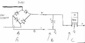
Ok, for the bridge, radio shack has at least two that will work. One is square, with leads out the bottom corners... a heavy duty device, there is also a small er one that is rectangular with all 4 leads out one of the small sides. Choose either, but double check me to make sure that the one you choose will handle at least 50PIV, and do 5 amps.

Althought I didn't mention it on the schematic, the input to the bridge, choose one line as positive, from the generator, and the other side will be ground from the generator ( or frame as it is most likely common ground )

The capacitor is any electrolytic with a 30v tolerance, preferable 100ufarads or better.

The regulators are a 7812 ( device number, not stock number ), this denotes a negative ground 12v regulator. They will be small, ( TO-220 ) size case, like your thumb nail.

The central tab is connected to the middle pin ( ground ). the left pin is voltage input, the right pin is regulated output.

Get about 7 of them and parallel them together. You can mount them to the metal bottom of a project enclosure if you wish ( it will heat sink them ).
These aren't the absolute best regulators for the job, as they will only handle 1 to 1.5 amps a piece.. but paralled like we have them will be sufficient. If you had a newark or skycraft store near you, you could get a heavier duty model.

I've made thousands of small regulated power supplies using componets like these. They work fairly well.
Between the final regulated output from the circuit, add an automotive style ( bus or blade ) inline fuse holder.. or get fancy, and add a bus style fuse holder to your circuit board if you use a board... Choose probably a 10 amp fuse.

This setup should easilly handle the 5 amp dynamo you have.

Anyway, if you choose this, have fun! It is a fairly simple circuit.

Soundguy
 

Attachments

  • 49-145662-CHARGE.jpg
    49-145662-CHARGE.jpg
    4.4 KB · Views: 153
   / Charging problem #112  
Soundguy, a full charged battery has a static voltage of 12.6, this is a higher downstrean voltage then your 12 volt Zenner trim circuit will allow. No way to get amps into battery unless you over come that battery CEMF, how about considering a zenner (regulator) around 14.5 volts instead.
Question, why are we running output current through another bridge rectifier outside of alt?
I was under the impression that he has already rectifed DC coming out of this alternator. I was confused before about this before, I am really confused now.
The cap is a good idea for cleaning up any AC ripple current still may be left after the diodes and most alternators have a cap built into alt for this purpose.
But do you think we need another set of rectifiers here?

Greg also mentioned 6 drag pts on one rotation of the field rotor, so it looks like he may have a three phase alternator.
That's a plus.
 
   / Charging problem #113  
I thought about all the possibilities and came to the conclusion, that this was the easiest circuit to build for him, not the best one. If I was doing it myself, I would go with a series pass regulator circuit and a 2n3055 transistor. As for the battery potential, with use ( probably first crank over, or load via lights, etc, ) battery potential should fall quickly, so that the 12v output will provide positive current flow.
The bridge is merely a safety device. I'm not at all sure of the condition of this guy's generator, or output setup ( guessing 3 phase, etc? ) whatever it is, and have not seen the internals, etc. The extra junctions are providing a negligible forward voltage drop on the un regulated side, and if alt. failure occours, may add a bit of protection to the rest of hte system. Also, if the tractor is ever jump started, could come in handy there as well. Ive seen bad effects of reverse polarity jumps , and 6v>12v, and 24v>12v jumps.
If he is rock solid about his output rectifier, then he can omit the bridge in the circuit. If he wants to go for a zenir circuit, he probably should pick up the mini eng's notebook on semiconductors that Mims writes for radio shack. It will answer his questions about the zenir circuit, and provide more schematics for him to look at, as well as give him a small 'session' on dc power supplies, etc.
I'm not sure if radio shack sells a 7815 but if so, they could be substituted in the schematic, and then add an epoxy rectifier or two in line with the output ( constant current regulator via diode junction ). That would be even better.
Too bad there are no real good electronic supply houses around anymore... unless you are lucky enough to live next to a skycraft or something.

Soundguy

"Soundguy, a full charged battery has a static voltage of 12.6, this is a higher downstrean voltage then your 12 volt Zenner trim circuit will allow. No way to get amps into battery unless you over come that battery CEMF, how about considering a zenner (regulator) around 14.5 volts instead.
Question, why are we running output current through another bridge rectifier outside of alt?
I was under the impression that he has already rectifed DC coming out of this alternator. I was confused before about this before, I am really confused now.
The cap is a good idea for cleaning up any AC ripple current still may be left after the diodes and most alternators have a cap built into alt for this purpose.
But do you think we need another set of rectifiers here?"

Greg also mentioned 6 drag pts on one rotation of the field rotor, so it looks like he may have a three phase alternator.
That's a plus.
 
   / Charging problem #114  
As a side thought, what do you think about expirementing with a low value resistor placed between the ground reference of the 7812 and ground. Should provide a higher output voltage... perhaps a variable resistor could be used, then he could 'dial in' a resistance he wanted, to achieve a range of voltage he was ok with. The resistance of the var. resistor could then be measured and he could use an appropriate higher wattage fixed resistor.

I've also seen diodes placed inline with the ground reference of the vr, accomplishes the same thing as the resistor idea.. just goes about it differently due to the forward voltage drop of the silicon junction, etc.

I'm afraid though, that this is going to get a bit complicated for this fellow though.....

Soundguy
 
   / Charging problem #115  
Ok, here is some further research.

Radio shack used to carry the 7815 vregs, but they went to mail order only, and may not even have them anymore. ( fo rthose people with old 'country store' radio shacks.. sometimes you may find old parts still in stock, etc ).

Anyway, the 7815 is in a 1 an 1.5 amp ( and .5 amp ) model.
they are special order #'s 900-4505 and 900-4506 ( 1 and 1.5 ) (.5 is 900-4504 )

Any of them would work.. size and amount will determine the charging capabilities of the system. For just replenishment, 5 amps is fine.. as that is all it was rated for anyway right?

In case those can't be found, he could get squirly and do some head games and isolate his regulator circuit, and use the still available 7915's ( negative voltage regulators.... just switch polarities, and stay isolated. )

The bridge I mentioned is a 276-1185 ( 25a, 50 PIV ) and the diodes I was thinking of were 276-1661 same stats.

As an off note, radio shack still sells the lm317t (and K ? )
adjustable regulator. the 't' model is rated at 1.5 a, and is in a to-220 package # 276-1778. The 'k' I think is in the larger to-2 case, and should do 15 amps, I don't have a part number for it. A small support circuit and the t0-2 lm317k would make a fine regulator for him. Your opinion?

As another side thought, does anyone make a prepackaged true voltage regulator ( not a field current regulator like most alt's use? ) If so... he may be better off getting one of those, unless he wants to do some soldering. A toss up. I know what I would do, but then I've been known to do a 40$ repair on a 25$ part, just to add an option or feature, and just to have fun, etc...

If newark electronics is still in business.. maybee he could order (5) 7815's and a capacitor wire them up and be done with it.

So I guess this is the 'dc power lab forum' now right?

Soundguy
 
   / Charging problem #116  
Whew,
I'm a bit confused. IF I do this, I will plan to use the existing bridge. The rest of the circuit is simple, but you started out recommending 7812 regulators, then changed that to 7815 - is this a 15volt regulator? Then you recommended I "add an epoxy rectifier or two in line with the output (constant current regulator via diode junction)". What is all this and is it necessary. Can I just substitute the 7815 for the 1812 or do I then end up with a 15volt regulator, and that would be too much? As I remember it, when the battery was new, I measured it at 15volts.

Putting a resistor between the ground reference of the 7812 and ground increases the zero reference voltage and therefore increases the regulated output voltage relative to ground? That would allow me to "tune" in the regulated voltage - right?

Also, you indicate that the capacitor should be 100uF or better. You mean a minimum of 100uF and that a 120uF or 150uF would be better? How high should I go?

By the way, component availablity isn't a problem. We have a number of guys here at work who build little prototype circuits all the time. I'm sure I can have them get any of these parts for me.

Greg
 
   / Charging problem #117  
"Whew,
I'm a bit confused. "

I'm sorry, that is my fault.. I tend to have rambling thoughts.


"IF I do this, I will plan to use the existing bridge. The rest of "

Yeah, if your bridge is functioning correctly, and producing dc voltage, that is all you need.. no need to purchase another bridge.

"the circuit is simple, but you started out recommending 7812 regulators, then changed that to 7815 - is this a 15volt "

I had originally thought that only 7812's ( 12v positive regulator ) were available, but found that there is the possibility that some people will carry a 7815 ( 15 positve reg. )

The 7812's would work ok, but your charging voltage would only be 12... it would be prefered to be a bit higher, but 12 would get you by. As a way to float it a bit, a small value resistor can be added between the grnd ref. of the regulators and ground to give you a slightly higher output voltage. Not exactly the best way to go about it, but what the heck.

If you can get your hands on the 7815 or equivalent.. they will be more suited. Some may argue that 15 is too high a charging voltage, and in some cases I will agree.. some sensitive electronics may not tolerate much above 14.5... seems funny.. but that .5 volt can sometimes make a difference to a marginal piece of equipment. If 15v is a problem, still use the 7815's, but inline with the output, put a couple of the 6amp/50piv diodes i mentioned in series.. the will have a forward voltage drop from their junctions, and will drop the charging voltage down to a more reasonable level. Also, this is less 'black magic' than the resistor in the ground reference for the 7812's, as some vregs don't like artificially inflated reference.. ( makes fryodes outta them.. or SMD - smoke emitting diodes /w3tcompact/icons/smile.gif ). The diodes in line with the 7815's actually form a circuit known as a constant current regulator, especially since you have a fixed source, that has a limited, pre-determined output ( dynamo ). The 7812's and 7815's can do up to 1.5 amps... 5 should be plenty.... just parallel them.. the diodes ( if you use them ) are rated to 6 amps, again... gives you 1a of tolerance if it is indeed a 5a charging system. Parallel two, then add another set of 2 paralleled, in series... 4 diodes ( 2 paralleled, and two parralleled... allows for 12amps current, and gives you 2 forward junctions to overcome for voltage drop.

""regulator? Then you recommended I "add an epoxy rectifier or two in line with the output (constant current regulator via diode junction)". What is all this and is it necessary. Can I just substitute the 7815 for the 1812 or do I then end up with a 15volt regulator, and that would be too much? As I remember it, when the battery was new, I measured it at 15volts.""

I changed my mind on the epoxy rectifiers, as I havn't seen any lately on the shelf that handle more than 3amps... the other ones I listed will do 6a.. and are sold in a 4 pack for like 2.99.


""Putting a resistor between the ground reference of the 7812 and ground increases the zero reference voltage and therefore increases the regulated output voltage relative to ground? That would allow me to "tune" in the regulated voltage - right?""

Youre on the right track. Sometimes they get alergic to this, and emit smoke... 7815's will be better if you can get them.

"Also, you indicate that the capacitor should be 100uF or better. You mean a minimum of 100uF and that a 120uF or 150uF would be better? How high should I go?"

Sure.. for dc power supplies.. bigger is *generally* better when filtering.. I wouldn't go overboard though.. in a high load situation, you'll have an averaging effect anyway. don't go over 1000u unless you get a good deal.. sometimes you find an assortment with a 2200u or a 4800u or even a 6000u in there as a goody.. but most of the big ones have a tolerance of like 15-16v.. so you need to hit somewhere around a 25v tolerance to give you some built in design failure protection.

"By the way, component availablity isn't a problem. We have a number of guys here at work who build little prototype circuits all the time. I'm sure I can have them get any of these parts for me."

That is excelent! wish I had friends like that.

Sounds like you are off to a good start.

Soundguy
 
   / Charging problem #118  
Soundguy & Greg, for what it's worth, most likely not much, here is my idea for cheapo voltage limiter circuit.
The ballast reisistor shown can be found almost anywhere for a few bucks. The hi amp zenner, however, may take some work. Low amp zenner units in parallel will also work here.
A 12 volt regulator would not work at all since battery voltage, with engine running, is almost always above the standard 12.6 volts. The 15 volt unit, though a bit high, should fly.
Don't confuse battery surface charge voltage with true battery voltage when checking batteries.
This is my first attempt to put a schematic on the net, I hope it works.

cheers,
 

Attachments

  • 49-146274-Zennercircuit,Yanmar.jpg
    49-146274-Zennercircuit,Yanmar.jpg
    34.8 KB · Views: 160
   / Charging problem #119  
Keoke,
Thanks for the drawing. So far, I have found 15volt zener diodes in 1, 5, and 50 watts. Nothing is rated in Amps. What do I need in terms of watts. I assume that the ballast resistor is a coil of ni-chrome wire wrapped on ceramic of some sort?

Greg
 
   / Charging problem #120  
Wow! What a thread...

Comments (from an electrical engineer):

-Putting 78xx and 79xx VRs in parallel is a bad idea. I am fairly certain that they will suffer from secondary breakdown without proper current balancing circuitry, however, it will work because of they are thermally protected. They will probably turn on and off like Xmas tree lights, and they will take turns running very hot. Even though they are rated for permanent shorting, it is best to derate the specs of components in circuit designs to prevent failure from long term heat damage.

-There is no feedback to the alternator on the few tractors I have seen.

-The zener diode idea is technically correct, but it requires a rather large and expensive zener diode to dissipate that much heat, so it is not the most practical design.

-The relay idea might work with sufficient filtering, but relays are generally slow for regulation response (which stresses other components in the system) and the rapid duty cycle to reach a steady state combined with tractor vibration and a high switching current on the contacts would likely cause the relay to eventually fail.

-The output from the full bridge rectifier is a DC signal at twice the frequency of the original AC signal. The ground reference (that makes it a DC signal) is relative only to the tractor chassis. You could use any any reference for anaylsis, and the frequency component of the signal will be present.

-The wires in the 1110D schematic are not correctly connected to the full bridge rectifier. The Y wire should connect from the VR to point R on the rectifier. The R wire should connect from the VR to the + side of the battery. For the 186D, there is also a wire for the battery voltage feedback from the keyswitch to the VR and a lamp indicator wire output from the VR.

I looked in my service manual for the 186D, and it the VR is a fairly complicated gadget. The VR is really a current limiter (as specified in the manual), and simply uses a zener diode as a reference voltage (to compare to the battery voltage) which is then used to bias a transistor (current switch) and reisistive load pair. The pair reach a steady state of shunting excess power and charging the battery based on the battery voltage. This is a more cost effective and elegant approach then the above mentioned zener circuit. Now for the complicated part. The VR actually has seven modes of operation (2 for starting, 2 for charging, 2 for no battery, and one that I forgot), and this includes additional circuitry to protect the alternator, battery, and the VR for reverse polarity.

Long story short, it would be an interesting project to build a VR, but probably not cost effective if you include the protection circuitry, additional modes of operation, and packaging. I am certain there are lots of alternate VRs available that would work great and cost less (like the Datsun one!), the trick is to find the information to cross reference and/or check the circuitry compatiability.

Or you could keep it simple with a with a zener diode, transistor, load resistor, and heat sink...

Keith
 

Tractor & Equipment Auctions

2012 Honda Accord LX Sedan (A51694)
2012 Honda Accord...
2019 Toyota Corolla Sedan (A51694)
2019 Toyota...
2006 Reelmaster Toro 3100D Mower (A50324)
2006 Reelmaster...
2001 Club Car Carryall Utility Cart (A51691)
2001 Club Car...
2015 PETERBILT 367 (A52472)
2015 PETERBILT 367...
2010 Ford Edge SE SUV (A51694)
2010 Ford Edge SE...
 
Top