Scoops,
Thanks for getting back with me. I have spent some time riddling what is going on with mine and have a cub dealer that is working though their “trouble call” system with the cub cadet dealers service. Here is what I know:
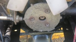
1. The 6284 tach sensor is located on the right side of the motor at the front and is right behind the radiator overflow reservoir. The sensor gets a signal from “high points” on a pickup plate which is held to to the crank pully with 3 countersunk hex screws.
2. My pickup plate became loose and actually rubbed the sensor until it wore through the epoxy tip and wore through the coil wire around the magnet which is in the middle of the sensor.
3. My sensor has two wires coming off of it. One of the wires is connected to two green wires.
4. The wire connected to the two green wires shorted against the frame and melted the connector and some of the wire going to the sensor.
5. The cub dealer said to check the sensor and it should have some resistance between the two wires. However my ohm meter reads infinite resistance (open circuit). So, according to the dealer it is bad.
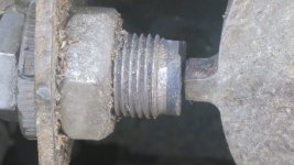
I did not learn that the pickup plate was loose until the tachometer failed. And, it is a good thing that I tightened the plate because one of the hex screws had fallen out and the other two were very loose. This could have failed the radiator fan and cost some serious money to fix. The work doesn’t take long to do; but, the radiator does have to be removed to get to the plate. And, while it is more money than it is worth ($100) for the sensor, I believe having a cub dealer that will submit trouble calls to the dealer support group is worth the investment.
But, here lies the dilemma which is “have I fried or burned any of the wiring or components on the tractor besides the tach sensor?” Supposedly, these sensors rely on the Hall Effect and likely have a power supply to them as opposed to a pickup coil variable reluctance sensor (
http://www.autoshop101.com/forms/h36.pdf) which does not require a power supply. Here is an article –
http://www.motor.com/magazine/pdfs/092006_07.pdf that you might be interested in reading as well. One reason for saying that this is likely a Hall Effect sensor is that the wires on mine melted – indicating a 12V supply power (whether in the start or run position. However, there was not any fuse blown and I don’t have a schematic to track the wiring down. When I do trace one of the green wires down, it goes to what appears to be an oil sending unit (my owner’s manual shows a tube going to the unit as an “oil line”. I pulled the plug off this I do get 12 v coming into the unit via the other wire (orange) on the sending unit (I believe the switch was in the run position). So, it is possible that this unit has failed (but, again no schematic - ). It is most puzzling to me as to why there would be two green wires tying into the one wire on the sensor. I guess it is possible that one is fed from the “start” circuit and the other is fed from the “run” circuit.
When my sensor comes in, I will know if all is ok simply by hooking it up and giving it a try (registers RPM on start and run). Otherwise, if it is ok with you, I may ask you to check voltage for me on each of the green wires during start and run just to help me trouble shoot.
Let me know if I can help trouble shoot yours.
mark
")