westcliffe01
Veteran Member
The picture I showed was from a low slung hot rod. Many coil sprung 4x4's use them and they are then above the axle. Range rover being one of the first examples, except that they had a slightly more complicated 3rd arm in the middle with a fancy ball joint. But it again only worked because they had a rigid axle connecting the 2 wheels together.
You can't use a motorcycle rear trailing arm design on a 4 wheel vehicle. Motor cycles lean into corners so they do not have side loads the way a 4 wheel vehicle will have which does not lean. The motorcycle style design would quickly be destroyed in your application. You need to have your suspension design absorb all lateral and torsional forces. That could be all of the vehicle weight on 1 wheel at a 45 degree angle in some cases. Not exaggerating..
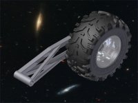
The simplest solution would be to use something like a straight trailer axle (2 hubs connected by a straight tube), use 2 radius rods like what you have in mind + 1 panhard rod behind the tube of the axle. The radius arms control the fore and aft forces, resist the torsion of the drive system and braking as well as the vertical suspension reactions. The panhard rod controls any lateral movement. Your radius arms would just have to attach to the top and bottom of the axle "tube" to be able to resist the torque. You may be able to get such radius arms ready to go from a vehicle like the Land rover. This is what they look like

You can't use a motorcycle rear trailing arm design on a 4 wheel vehicle. Motor cycles lean into corners so they do not have side loads the way a 4 wheel vehicle will have which does not lean. The motorcycle style design would quickly be destroyed in your application. You need to have your suspension design absorb all lateral and torsional forces. That could be all of the vehicle weight on 1 wheel at a 45 degree angle in some cases. Not exaggerating..
The simplest solution would be to use something like a straight trailer axle (2 hubs connected by a straight tube), use 2 radius rods like what you have in mind + 1 panhard rod behind the tube of the axle. The radius arms control the fore and aft forces, resist the torsion of the drive system and braking as well as the vertical suspension reactions. The panhard rod controls any lateral movement. Your radius arms would just have to attach to the top and bottom of the axle "tube" to be able to resist the torque. You may be able to get such radius arms ready to go from a vehicle like the Land rover. This is what they look like
Last edited: