Here are the ACTUAL Lift Capacities of the RK24 L75 FEL @ Varoius Heights (w/ Graph!)

   / Here are the ACTUAL Lift Capacities of the RK24 L75 FEL @ Varoius Heights (w/ Graph!)
  • Thread Starter
#21  
At least you have a good sense of humor.

The math (if you like math) is the easy part. Its actually understanding the concepts and how to apply the math that give most people fits.

I like it all. I'm a designer/draftsman by day, and a jack of all trades in my free time, so being able to apply math to solve real world problems is fun for me. Crazy, I know. And what is life without a sense of humor! :dance1:

I was actually thinking about modeling up a simple representation of this in CAD and running an analysis on it that way. That would be the ultimate, but would be overkill for this.

I might go ahead and rerun my scale test though, when I get time, being extra careful to keep everything in line, even, and vertical.
It would be nice if the real world testing approximated the theoretical force curve and values more closely.
 
   / Here are the ACTUAL Lift Capacities of the RK24 L75 FEL @ Varoius Heights (w/ Graph!) #22  
Wouldn’t it be a lot easier to figure out the ratio between the distance the loader pins move and the cylinder stroke? That method would fail to account for it being stronger at the bottom and would instead give an average. And you’ll need to know the psi the tractor is putting out.

Correct. It dont account for being stronger at the bottom. But does give a good average value for what the loader lifts.

I like it all. I'm a designer/draftsman by day, and a jack of all trades in my free time, so being able to apply math to solve real world problems is fun for me. Crazy, I know. And what is life without a sense of humor! :dance1:

I was actually thinking about modeling up a simple representation of this in CAD and running an analysis on it that way. That would be the ultimate, but would be overkill for this.

I might go ahead and rerun my scale test though, when I get time, being extra careful to keep everything in line, even, and vertical.
It would be nice if the real world testing approximated the theoretical force curve and values more closely.

Does your loader manual have a lift curve?
 
   / Here are the ACTUAL Lift Capacities of the RK24 L75 FEL @ Varoius Heights (w/ Graph!)
  • Thread Starter
#23  
Correct. It dont account for being stronger at the bottom. But does give a good average value for what the loader lifts.


Does your loader manual have a lift curve?

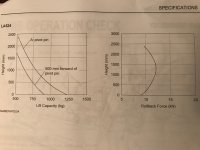
No. My comment was just in reference to an earlier reply about loader lift curves being more parabolic in shape and without the flat spots my original test showed.
 
   / Here are the ACTUAL Lift Capacities of the RK24 L75 FEL @ Varoius Heights (w/ Graph!) #24  
Here's a typical curve:

IMG_8072 (1).jpg
 
   / Here are the ACTUAL Lift Capacities of the RK24 L75 FEL @ Varoius Heights (w/ Graph!)
  • Thread Starter
#25  
No problem.

But the critical key is cylinder bore diameter. Cause without the MFG spec, its difficult to measure without guessing.

I am betting 40mm bore

You were right to guess 40mm.

Here are the measurements I took tonight.
The relief pressure was listed in the manual.
I ran a few calcs (on the right) but I'm not sure where to go from there with calculating the forces.
It's been a few years since my statics and dynamics classes in college and I'm afraid I've forgotten a lot of it. :-/

Thanks for the help!

fel_lift_calcs.PNG
 
   / Here are the ACTUAL Lift Capacities of the RK24 L75 FEL @ Varoius Heights (w/ Graph!) #26  
Interesting exchange of information. Great to see everyone engaged and contributing. Don’t want to get involved in the discussion about whether tests are done scientifically or not. The key thing we’d like to say with regards to lift capacity is that you can fill the bucket with gravel and dump it at full height. Pretty much all anyone needs to know other than the tractor is a system, and max lift capacities are often measured in consideration of the whole system. The loader can lift more than spec, but will put stress elsewhere putting other areas and safety at risk. Be careful out there, stay within practical limits.
 
   / Here are the ACTUAL Lift Capacities of the RK24 L75 FEL @ Varoius Heights (w/ Graph!) #27  
You were right to guess 40mm.

Here are the measurements I took tonight.
The relief pressure was listed in the manual.
I ran a few calcs (on the right) but I'm not sure where to go from there with calculating the forces.
It's been a few years since my statics and dynamics classes in college and I'm afraid I've forgotten a lot of it. :-/

Thanks for the help!

View attachment 596632

The first step is figuring the angle in which the cylinder's force is applied.

This isnt the angle with the ground, or any particular point that is easily measured. Thus the triangle measurements is all aI need. Knowing the Lengths of the 3 sides I can calculate the exact angle. (look up law of cosines for formula)

So we want to focus on triangle BDC, and in particular...we need to solve for angle B. And then EDC (when raised) to again find the angle of the cylinder

Law of cosines is a PITA to actually type out. I'll trust you can apply the numbers on your own and solve for angle B and E when raised? if not I can attempt to spell it out.

I come up with 21.08 degrees when lowered and 15.3 degrees at full raise.
________________________________________________________________________________
Step 2....Find the force of the cylinder.
40mm bore @ 2205psi = 4295 pounds of push force PER cylinder.

But cylinder mounted on an angle. To account for that, the vertical component of the lift force is the Sine of the angle.
So. Sin(21.08) x 4295 pounds x 2 cylinders =3090 pounds vertical force
....Sin(15.3) x 4295 x 2 = 2266 pounds vertical force at max lift
_______________________________________________________________________________________________
Step 3: The above is the lift force where the cylinder attaches to the loader. Now we need to figure how that relates to the Pin location

Now it becomes a lever......A-B-C with C the fulcrum, and B where the force is applied......At point A....you have 0.539% of force applied at B.

So at ground level, 1665#
At max height, 1221#
______________________________________________________________________________________________________
Step 4. This is a bit tricky to "actually" measure. Especially without a force gauge. And that is Just how much does the weight of the loader/bucket take away from the capacity? IT can be measured with a pressure gauge and reverse calculated. But given the "spec" is 947# to max height....and the cylinder force NOT accounting for the weight of the bucket/frame is 1221#....I'd say that's pretty close.
 
   / Here are the ACTUAL Lift Capacities of the RK24 L75 FEL @ Varoius Heights (w/ Graph!)
  • Thread Starter
#28  
Interesting exchange of information. Great to see everyone engaged and contributing. Don’t want to get involved in the discussion about whether tests are done scientifically or not. The key thing we’d like to say with regards to lift capacity is that you can fill the bucket with gravel and dump it at full height. Pretty much all anyone needs to know other than the tractor is a system, and max lift capacities are often measured in consideration of the whole system. The loader can lift more than spec, but will put stress elsewhere putting other areas and safety at risk. Be careful out there, stay within practical limits.

I definitely appreciate and heed the practical limits, but at the same time I like to understand and over-analyze everything. Guess that's just the designer/engineer in me.
 
   / Here are the ACTUAL Lift Capacities of the RK24 L75 FEL @ Varoius Heights (w/ Graph!) #29  
   / Here are the ACTUAL Lift Capacities of the RK24 L75 FEL @ Varoius Heights (w/ Graph!)
  • Thread Starter
#30  
The first step is figuring the angle in which the cylinder's force is applied.

This isnt the angle with the ground, or any particular point that is easily measured. Thus the triangle measurements is all aI need. Knowing the Lengths of the 3 sides I can calculate the exact angle. (look up law of cosines for formula)

So we want to focus on triangle BDC, and in particular...we need to solve for angle B. And then EDC (when raised) to again find the angle of the cylinder

Law of cosines is a PITA to actually type out. I'll trust you can apply the numbers on your own and solve for angle B and E when raised? if not I can attempt to spell it out.

I come up with 21.08 degrees when lowered and 15.3 degrees at full raise.
________________________________________________________________________________
Step 2....Find the force of the cylinder.
40mm bore @ 2205psi = 4295 pounds of push force PER cylinder.

But cylinder mounted on an angle. To account for that, the vertical component of the lift force is the Sine of the angle.
So. Sin(21.08) x 4295 pounds x 2 cylinders =3090 pounds vertical force
....Sin(15.3) x 4295 x 2 = 2266 pounds vertical force at max lift
_______________________________________________________________________________________________
Step 3: The above is the lift force where the cylinder attaches to the loader. Now we need to figure how that relates to the Pin location

Now it becomes a lever......A-B-C with C the fulcrum, and B where the force is applied......At point A....you have 0.539% of force applied at B.

So at ground level, 1665#
At max height, 1221#
______________________________________________________________________________________________________
Step 4. This is a bit tricky to "actually" measure. Especially without a force gauge. And that is Just how much does the weight of the loader/bucket take away from the capacity? IT can be measured with a pressure gauge and reverse calculated. But given the "spec" is 947# to max height....and the cylinder force NOT accounting for the weight of the bucket/frame is 1221#....I'd say that's pretty close.

Wow, thanks for all that!

A couple of questions, both regarding Step 3:
1.) Did you mean 53.9% (aka .539)?
2.) For the ratio of the 2 levers, I agree that the C-B distance should be used, but shouldn't we be using the C-A distance as the length of the overall lever? (Instead of using the sum of C-B & B-A.) That would be the true radius, would it not? This would change the 53.9% to 55.4%, which in turn would increase the results slightly. 1712# & 1256# respectively.
 

Tractor & Equipment Auctions

2015 John Deere Z950M 70in Zero Turn Mower (A51691)
2015 John Deere...
John Deere 9470R (A53342)
John Deere 9470R...
2010 Ford Edge SE SUV (A51694)
2010 Ford Edge SE...
Deutz BF12L413F 19.1L V12 Turbo Diesel Generator (A51691)
Deutz BF12L413F...
2018 Club Car Carryall 500 Electric Utility Cart (A51691)
2018 Club Car...
2011 Autocar ACX64 Xpeditor coe t/a refuse (A52384)
2011 Autocar ACX64...
 
Top