How Massey Ferguson GC 1723 & 1725 hydraulics are plumbed

   / How Massey Ferguson GC 1723 & 1725 hydraulics are plumbed
  • Thread Starter
#21  
Nice work. I used to draw one-line hydraulic diagrams for work that were more pictorial with valve layouts, labeled ports, hose sizes, etc., used in a production environment where JIC schematics were not necessary but helped speed of assembly. I will find one somewhere and post back. Any chance you could do this 😁
I can try; thx.
 
   / How Massey Ferguson GC 1723 & 1725 hydraulics are plumbed #22  
These diagrams and pictures are amazing.
I plan to add rear remotes to my GC1723E and these are extremely helpful.

Thanks.
 
   / How Massey Ferguson GC 1723 & 1725 hydraulics are plumbed
  • Thread Starter
#23  
Nice work. I used to draw one-line hydraulic diagrams for work that were more pictorial with valve layouts, labeled ports, hose sizes, etc., used in a production environment where JIC schematics were not necessary but helped speed of assembly. I will find one somewhere and post back. Any chance you could do this 😁

I can try; thx.

Hi @polarred21,

Can you send a sample of what you have in mind?

Thx, Dick
 
Last edited:
   / How Massey Ferguson GC 1723 & 1725 hydraulics are plumbed
  • Thread Starter
#24  
These diagrams and pictures are amazing.
I plan to add rear remotes to my GC1723E and these are extremely helpful.

Thanks.

Thank you and welcome to both the Forum and the "GC Club".

I am remiss in posting any of the diagrams for my ongoing updates with remotes (a work still in progress). However, basically you have to break into the "power beyond" line (#6) from the loader valve to the backhoe (assuming you have one), otherwise the "power beyond" line (#11) from the loader valve back to the "control valve", to feed the new rear remotes valve(s). All must be in series and the valve(s) need to be open center and have power beyond capability. You also need to add a drain/return line back to the sump (transaxle housing) and this can be tee'd into an existing one.

Good luck and please update us with your progress, Dick
 
Last edited:
   / How Massey Ferguson GC 1723 & 1725 hydraulics are plumbed #25  
Hi @polarred21,

Can you send a sample of what you have in mind?

Thx, Dick
My apologies, I have to access my old .dwg files at work, but I will get you some samples of what I was referring to.

Here is something atypical from a 3rd function kit, would need to know what all the GC valves look like if available.

WR Long Atypical Hydraulics Drawing.jpg
 
Last edited:
   / How Massey Ferguson GC 1723 & 1725 hydraulics are plumbed
  • Thread Starter
#26  
My apologies, I have to access my old .dwg files at work, but I will get you some samples of what I was referring to.

Here is something atypical from a 3rd function kit, would need to know what all the GC valves look like if available.

View attachment 3221518
Wow, that's a tough order; I'm not particularly adept at freehand drawings. I can certainly send you photos of the valves either here or by email if that's what you're asking for. And yes, I can work with *.dxf (or *.igs) files.
 
   / How Massey Ferguson GC 1723 & 1725 hydraulics are plumbed
  • Thread Starter
#27  
I want to add some finishing touches to this thread, before I start a new thread on all the revisions I have done. From my original post:

"11 In paragraph 8 I discussed the dividing valve within the control valve, and the power beyond line to the steering valve. I won’t delve into this anymore at this time as it is fairly well covered in the service manual, except that the “tank return” from the steering valve really doesn’t go to the tank. It actually is tee’d to go two places. One is the PTO (power takeoff clutch, which I won’t go into as I haven’t used and studied that), and the other is (finally!), the filter. From the filter, the fluid runs to the hydrostatic transmission. So, the transmission is the only component that is working with freshly filtered oil, and the only component that returns relatively clean oil to the tank! As far as I can tell, it is only the flow through the transmission that gets really filtered. Everyone else is taking what feeds back to the tank through various components (and isn’t filtered either before or after use) and is then only strained on its way to and from the pump."

To update this on the PTO:

The PTO clutch is a series of wet plates that are engaged hydraulically. In this screen print from the service manual, the clutch pack is just to the left (forward) of the arrows from the #8 balloon. Those arrows are pointing to two O-rings that run on the shaft. Further aft, behind the gear and the bearing are two more O-rings (balloon #2). Hydraulic oil is injected through the passageway by balloon #1 into the hollow shaft between the aft O-rings, through the shaft, and exits the shaft between the forward O-rings.
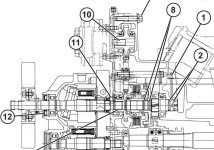
Massey Ferguson GC PTO clutch pack & seals 1.jpg

Two more screen prints from the parts manual. The PTO clutch pack is #45, the forward O-rings are #46, the shaft is #41, and the aft O-rings are #42.
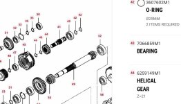
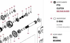
Massey Ferguson GC PTO clutch pack & seals 2.jpgMassey Ferguson GC PTO clutch pack & seals 3.jpg
 
   / How Massey Ferguson GC 1723 & 1725 hydraulics are plumbed
  • Thread Starter
#28  
Further, to update my first post regarding the steering gear, the system used on the Massey Ferguson GC tractors is used extensively on other tractors and off-road equipment. It is a completely hydraulic system with no mechanical link, i.e., if a hydraulic line in the system breaks, or if there is no fluid, turning the steering wheel will not have any effect on the hydraulic steering cylinder, unlike the power steering in a car or truck. There is a mechanical link from the steering wheel to the valve, but none to the front wheels.

The control valve is known as an Orbitrol (sometimes spelled Orbital). It consists of a complex spool valve and a "Gerotor". Basically, when you turn the steering wheel, the spool valve shifts a little and provides hydraulic fluid to one side or the other of the double ended steering cylinder. It also feeds some fluid to the Gerotor which acts as a hydraulic motor and feeds back to the spool valve. But if there is no hydraulic oil flow provided, as is the case when the engine is not running, the Gerotor acts as a pump and moves the spool valve, although you have to grunt to turn the steering wheel.

The GC service manual schematic denotes this Gerotor strictly as a motor, but every other schematic I have seen shows it as a motor-pump or Gerotor, so I have depicted it that way on my latest revised schematics (to come soon).

Here is a video (there are others) explaining the system: how does an orbitrol valve work? - Search Videos
 
   / How Massey Ferguson GC 1723 & 1725 hydraulics are plumbed
  • Thread Starter
#29  
Here are the revised schematics, with and without a backhoe. I have updated some of the line fonts, made a few changes to (hopefully) make these easier to understand, yada, yada, yada. Please review the "colors/notations/legend" section in the upper right as some of mine are unusual, again in the hope that it clarifies things.

Again, I have posted a picture of the schematics and then pdf's of them so you can open them up and zoom in.

edit: replaced picture/pdf because a line was missing : (

original hydraulics.jpg
original no backhoe.jpg
 

Attachments

  • original hydraulics.pdf
    175.1 KB · Views: 2
  • original no backhoe.pdf
    144.1 KB · Views: 1
Last edited:

Tractor & Equipment Auctions

2018 GMC Sierra 1500 4x4 Crew Cab Pickup Truck (A50323)
2018 GMC Sierra...
2025 Kivel 48in Forks and Frame Skid Steer Attachment (A50322)
2025 Kivel 48in...
71069 (A49346)
71069 (A49346)
2000 KOMATSU VALMET 860.4 FORWARDER (A51222)
2000 KOMATSU...
Westendorf Gravity Wagon (A50514)
Westendorf Gravity...
71055 (A49346)
71055 (A49346)
 
Top