How Massey Ferguson GC 1723 & 1725 hydraulics are plumbed

   / How Massey Ferguson GC 1723 & 1725 hydraulics are plumbed #11  
I'm referring to the quick disconnects on the backside where you hook up hydraulically powered implements. In my case they are Pioneer, poppet style. release under pressure disconnects. I have 3 sets on each tractor.
 
   / How Massey Ferguson GC 1723 & 1725 hydraulics are plumbed #12  
I'm not sure what you are referring to. If by SCV you mean solenoid control valve, there is none in the Massey Ferguson OEM system. Please explain.
To me and I believe in most tractor service manuals SCV stands for Selective Control Valve. With many being spring centered after releasing the handle when it is operated in either direction, some will have detents in one or both operating positions, these are good for some motors, and then the harder one to find on the smaller tractors the valves with a float detent, in that position the ports in the SCV allow flow in and out at the same time.
 
   / How Massey Ferguson GC 1723 & 1725 hydraulics are plumbed
  • Thread Starter
#13  
I'm referring to the quick disconnects on the backside where you hook up hydraulically powered implements. In my case they are Pioneer, poppet style. release under pressure disconnects. I have 3 sets on each tractor.
Thanks for the explanation. I'm still a neophyte on hydraulics.

The factory does not supply any rear (or front) disconnects except for what's shown in my diagram for the loader and backhoe.

However, I now have four sets in the rear and will chronicle them when I get them working to my satisfaction, hopefully shortly. :)
 
   / How Massey Ferguson GC 1723 & 1725 hydraulics are plumbed
  • Thread Starter
#14  
To me and I believe in most tractor service manuals SCV stands for Selective Control Valve. With many being spring centered after releasing the handle when it is operated in either direction, some will have detents in one or both operating positions, these are good for some motors, and then the harder one to find on the smaller tractors the valves with a float detent, in that position the ports in the SCV allow flow in and out at the same time.
Thanks for the education. As I mentioned above to @5030, I am still a neophyte on hydraulics.

Yes, all the stock valves are spring centered, with a detented float for the loader, a non-detented quick dump for the bucket curl, and a detented float for the backhoe boom. The 3-point valve has a non-detented float, and is only a 3 position valve, not 4 position like the other two floats.
 
   / How Massey Ferguson GC 1723 & 1725 hydraulics are plumbed #15  
I am surprised that your backhoe valve stack has float position for the boom.
Yes, your 3 point valve is actually a single action valve, it only has power for lift down is all gravity.
 
   / How Massey Ferguson GC 1723 & 1725 hydraulics are plumbed
  • Thread Starter
#16  
I am surprised that your backhoe valve stack has float position for the boom.
Yes, your 3 point valve is actually a single action valve, it only has power for lift down is all gravity.
Yes the backhoe boom float is unusual. It is to help leveling the bottom of a ditch, etc. See:
 
   / How Massey Ferguson GC 1723 & 1725 hydraulics are plumbed
  • Thread Starter
#17  
Yes the backhoe boom float is unusual. It is to help leveling the bottom of a ditch, etc. See:
Funny thing about the backhoe boom float: Massey Ferguson has a service bulletin (23-0081) to add a dual pilot operated check valve on the backhoe boom circuit and reads “The backhoe boom can settle downwards if the operator uses the dipper function, bucket function, swing function or outrigger function while pulling back on the left hand joystick to raise the boom. A pilot operated check valve kit part number ACP0806600 must be installed in the boom cylinder circuit to prevent the boom from lowering under this operating condition. Note: Installation of the pilot operated check valve will delete the boom float function.” I was thinking of adding such a valve anyway as I wasn't using the float function, and it was a pain to always have to keep pulling the boom back up when not using it.
 
   / How Massey Ferguson GC 1723 & 1725 hydraulics are plumbed
  • Thread Starter
#18  
Massey Ferguson GC 1723EB hydraulics: update on original factory plumbing – updated from post #3

I have a 2022 Massey Ferguson GC1723EB TLB (tractor-loader-backhoe); her nickname is Fergie (named after the red-headed Sarah Ferguson, Dutchess of York). Much of this applies to other Massey Ferguson GC models.

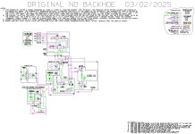
I am posting an updated schematic of the original plumbing on my tractor. I have extensively updated this since my previous postings: I have added load check valves within the loader valve, and removed the pressure relief valve that “I thought” was there. I have rearranged the major components to depict their shapes and positions more nearly (note where the power takeoff relief valve is!) especially with regards to where the external lines are connected, and which are hard lines or hoses (flex lines). The locations have been determined by looking at my machine, the service manual, the parts book, and other people’s postings. All the internal lines are drilled passageways in the housings, and I have shown them close to the actual location. The internal components of valves and hydrostatic transmission have been squeezed in to be “tidy” and may not be correctly located “within” that assembly. I have also added line numbers in boxes with notes listing them. The so-called ”flange cover” mounted on top of the control valve is just a fitting block. Beware that the service manual for this model has photos which are outdated and from previous models, as they show at least one fitting and hard line where I have nothing, not even a place for that fitting; also, there are some errors in the factory schematics. Likewise, the parts books can be “iffy.” The attached photo of the schematic design will be hard to read on the forum, but I have attached a pdf file of it which you can open and be able to zoom in.

Here are some hydraulic relief valve pressure specs I have found:
- Main relief valve spec is 1920psi (blows off to tank).
- Steering pump relief valve spec is 1209psi (blows off to steering pump pressure beyond).
- Backhoe relief valve spec is 2175psi (blows off to tank).
- Hydraulic filter bypass spec is 14.2psi.
- Hydrostatic transmission high pressure relief valve spec is 2554-2700psi (blows off to other side of hydraulic loop).
- Hydrostatic transmission charge pressure relief valve spec is 57-85psi (blows off to tank – actually, I think it just blows off inside the HST housing and that housing has an overflow port to the transmission front cover located near the top).

But what is the setting for the power takeoff relief valve? As far as I can determine/figure/guess, the power takeoff relief valve and the power takeoff clutch valve are fed from power beyond of the steering valve. It appears that the power takeoff relief valve is always activated except when the power takeoff clutch valve is activated. And even when the power takeoff clutch valve is activated, it probably only takes a small amount of hydraulic fluid to lock the clutch, and then the power takeoff relief valve is again activated, although this may slowly cycle on-and-off to compensate for slight leakage. And it is only when the power takeoff relief valve is activated that any oil is fed to the hydraulic filter and then to the hydrostatic transmission. I guess that this relief valve is set at a far lower pressure than the main relief valve (likely around 100psi), and that is probably why it doesn’t seem to squeal when (always?) activated. This flow to the hydrostatic transmission is just the “charge flow”, which makes up for internal leakage within the HST.

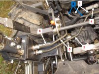
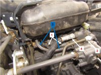
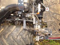
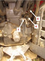
I am also posting some photographs of my machine with the fender/skirt and seat removed and the fuel tank moved aft that I have marked line numbers on that correspond with the line numbers on the schematic. There is no significance to the callouts for line #3 being blue in the pictures, it just to make sure it is not confused with the adjacent line #1.

<deleted 3/2/25 - see next post>

Since you won't be able to read this on the forum, I am attaching a pdf file of it (sorry, it's down below the thumbnails): <deleted 3/2/25 - see next post>
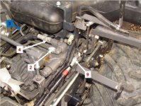
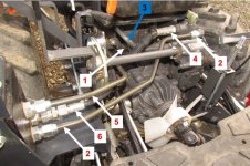
hydraulic lines 1.jpghydraulic lines 2.jpghydraulic lines 3.jpghydraulic lines 4.jpghydraulic lines 5.jpghydraulic lines 6.jpghydraulic lines 7.jpg
 
Last edited:
   / How Massey Ferguson GC 1723 & 1725 hydraulics are plumbed
  • Thread Starter
#19  
Massey Ferguson GC 1723EB hydraulics: update on original factory plumbing – updated from post #18

Once again, a new update:
- 12/7/24 file had some errors
- tried to simplify
- made the "no backhoe" version a separate drawing

Since you won't be able to read these on the forum, I am attaching pdf files of them.

I finally found a spec for the power take-off relief valve in an earlier service manual; it is 79 psi.

original hydraulics.jpg

original no backhoe.jpg
 

Attachments

  • original hydraulics.pdf
    153.6 KB · Views: 35
  • original no backhoe.pdf
    122.2 KB · Views: 33
   / How Massey Ferguson GC 1723 & 1725 hydraulics are plumbed #20  
Nice work. I used to draw one-line hydraulic diagrams for work that were more pictorial with valve layouts, labeled ports, hose sizes, etc., used in a production environment where JIC schematics were not necessary but helped speed of assembly. I will find one somewhere and post back. Any chance you could do this 😁
 

Tractor & Equipment Auctions

2019 SALVATION TRAILERS (A45046)
2019 SALVATION...
20 YARD ROLL OFF CONTAINER (A45046)
20 YARD ROLL OFF...
2013 FREIGHTLINER CORONADO 122 SD (A45333)
2013 FREIGHTLINER...
YANMAR VIO35-5 (INOPERABLE) (A45333)
YANMAR VIO35-5...
1994 FRUEHAUF 45FT FLATBED TRAILER (A45333)
1994 FRUEHAUF 45FT...
HYDRAULIC SQUEEZE OFF (A45333)
HYDRAULIC SQUEEZE...
 
Top