I want to add some finishing touches to this thread, before I start a new thread on all the revisions I have done. From my original post:
"
11 In paragraph 8 I discussed the dividing valve within the control valve, and the power beyond line to the steering valve. I won’t delve into this anymore at this time as it is fairly well covered in the service manual, except that the “tank return” from the steering valve really doesn’t go to the tank. It actually is tee’d to go two places. One is the PTO (power takeoff clutch, which I won’t go into as I haven’t used and studied that), and the other is (finally!), the filter. From the filter, the fluid runs to the hydrostatic transmission. So, the transmission is the only component that is working with freshly filtered oil, and the only component that returns relatively clean oil to the tank! As far as I can tell, it is only the flow through the transmission that gets really filtered. Everyone else is taking what feeds back to the tank through various components (and isn’t filtered either before or after use) and is then only strained on its way to and from the pump."
To update this on the PTO:
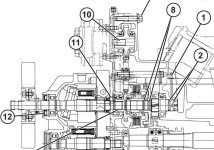
The PTO clutch is a series of wet plates that are engaged hydraulically. In this screen print from the service manual, the clutch pack is just to the left (forward) of the arrows from the #8 balloon. Those arrows are pointing to two O-rings that run on the shaft. Further aft, behind the gear and the bearing are two more O-rings (balloon #2). Hydraulic oil is injected through the passageway by balloon #1 into the hollow shaft between the aft O-rings, through the shaft, and exits the shaft between the forward O-rings.

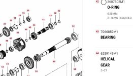
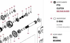
Two more screen prints from the parts manual. The PTO clutch pack is #45, the forward O-rings are #46, the shaft is #41, and the aft O-rings are #42.


