swnoel
Silver Member
Thanks!
Also something else.
There's no hydraulic oil filter on the loader. I want to add one. Does it go on the high pressure line before the valves? Or on the return line before the reservoir? Or after the reservoir?

To clarify, galvanized pretty much means plumbing fittings designed for under 200-300psi, not hydraulic fittings generally designed for 3,000psi.Chris
Do not forget to replace the four 90 degree galvanized elbows on top of the FEL valve which have the hoses to the FEL work cylinders connected to them
Dave M7040


ok the backhoe is hooked up and it works!
its actually quite speedy with the tractor at 1000rpm with decent power. maybe a bit too speedy actually haha.
however i do have a question -
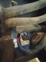
on the 2 cylinders that control the left to right swing. theres these nuts that screw on to what im guessing would be where a return hose would go.
View attachment 552571
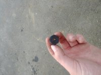
when i first tried that backhoe functions and swung to the left a bunch of fluid sprayed out. i assumed a hose was blown but looking closer it was coming from the bolt. i took it off and the bolts have a hole in the top.
View attachment 552570
its like a breather almost. after the first bunch of fluid came out it seemed to stop doing that. im guessing some fluid leaked through some seal over the time it was sitting. you can hear air blowing through when you go left to right now.
im wondering if this is how its supposed to be? should there be a filter of some kind on them?

All the other cylinders on the backhoe are probably double acting, so they don't need a breather like that one does.Ah ok great. I'll have to get a proper one. Whoever made this just had what look like some couch cushion stuff through the hole to act as a filter.
Why would these cylinders need a breather but not other ones?
Dave,do you have a couple of pictures of this hooked up correctly? If you have a three point hitch, is a power beyond sleeve mandatory? Thanks DennisLet me combine two answers in one post.
Chris wants to add a temp gauge.
This electrical type would be the easiest. At the tank there is a return elbow for the fluid returning to the tank.
You install a tee instead of the elbow and in the open hole on the Tee you install the temp sensor using the necessary bushings.

The "assembly" beside the two control levers is the adjustable relief valve. Most open center farm tractor type loader valves have them.
Let me explain a little further. Should you have a power beyond circuit coming from the loader valve and going to a second control valve,for a top and tilt for example, the second control valve also has a relief valve.
The FEL relief valve is set at 2,200 psi just to pick a figure. No matter what you do to the relief valve on the top and tilt control, it will never produce pressures higher than the FEL relief valve as the FEL relief is dumping any pressure above its setting. If you wanted the top and tilt relief valve set to 1,500 psi, you can do that and not affect the FEL pressures as they are first in line from the pump.
Please don't hesitate to ask any question. We all started with no knowledge at one point and it is the obligation for a few like me who have a bit more to share with others who want to learn.
Currently Chris' loader valve has a return line to the tank or reservoir. This is necessary for several reasons but a critical one is to provide a place for the relief valve to get rid of excess pressure.
On his normal loader valve there is a high pressure supply from the hydraulic pump. there are 4 work lines going to the double acting lift arm and bucket cylinders.
One high pressure supply line
One tank or return line
Four work lines
Total of six
Six is the basic number of lines a double spool FEL valve must have.
If there is a seventh line, that tells me that it is a power beyond line because it is above the number for simple FEL operation.
Sometimes you find uneducated people using the tank port to feed another hydraulic circuit. They cannot see why a line, which has fluid flowing in it, cannot be a pressure line for another valve.
There are design reasons too complicated to go into why this is a bad practice but the specification of most valves shows a simple reason not to do it.
The green arrow shows the design working pressure of the valve. The red arrow shows the much smaller design pressure of the tank port.

The only reason it is even 500 psi is in case you are using the tank port to supply a return line filter which creates some restriction in the flow of oil going back to the tank or reservoir.
This is an example of where a power beyond plug or sleeve would go.

This next fancy sketch is the type of Google search find that seriously misleads owners. It is using the out or tank port of the first valve to feed the second valve.

It is both wrong and dangerous.
Another WRONG example this time from youtube.

Power beyond is also called High Pressure Carry Over HPCO which is a better term to describe what is happening.
More questions, just ask. i never give short answers
Dave M7040
I have a very similar valve:Dave,do you have a couple of pictures of this hooked up correctly?
That depends on the valve, you can have either six or seven ports coming out of a two spool valve like a loader valve, the odd numbered port will allow you to send low pressure return back to the tank and always have a place to dump fluid.If you have a three point hitch, is a power beyond sleeve mandatory? Thanks Dennis
Thanks!!A 2 spool Husco loader valve on our B7500's loader:
View attachment 784628
View attachment 784629
It has the following ports:
In = Inlet - High pressure in from the pump, labeled as P (Pump) in the diagram above
Out = Outlet - Low pressure outlet to tank, T (Tank) in the diagram above
PB = Power Beyond - High pressure outlet to the next valve, labeled as C (High Pressure Carryover) in the diagram above
Aaron Z
What is a fel valve?I see 6 hoses so if that is correct there is no power beyond at the present.
I also see galvanized plumbing street elbows used which is a big No No as they are not designed for the pressures in a hydraulic system.
Further, teflon tape is used everywhere to make improper fittings. That product contributes tiny strings to the hydraulic system which is bad for the pump and valves.
If you need another hydraulic circuit suggest you start with a new FEL valve with the correct hydraulic fittings and with a power beyond sleeve in it.
Alternatively, you install another single spool control valve ahead of the current FEL valve and then new valve feeds the old valve with its power beyond circuit.
Dave M7040