BandD,
After a few minutes looking at the exploded diagrams of your
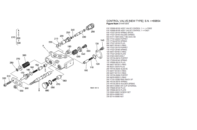
M59 hydraulic system, I'm beginning to get the picture of how the valve works. The input shaft (060) from the position control lever has a crank arrangement on that end, and so does the feedback lever shaft (140) on the other side.
They both impart a twisting motion on an intermediate shaft (050) that goes in the middle. That has a pivoting offset "finger" (020) that presses on one of the spools in the control valve. It's hard to tell which one, but I think it's (B). The other one has a nylock type nut on it, and what looks like an allen head recess for adjustment.
"H" is a straight shaft, and acts as a pivot point for the flat plate. That's the reason the hole in the plate is elongated, because it has to pivot around the shaft on "H".
As the position control valve is moved, the input side moves, rotating the intermediate shaft and pressing the finger against the valve spool to open the valve. The 3 point raises in response until the feedback shaft rotates enough to move the intermediate shaft in the opposite direction until it moves the finger enough to allow the valve spool to close again and shut off the oil flow.
The only way I could see it being rough in operation is if there's a "dead band" between the spot where the supply spool opens and the feedback side closes it again. In other words, a "lag in communication".
For example, if you've ever used a satellite phone or secure communications link, there's a time lag between the time you speak and the time the other person hears you. It makes for a jerky conversation until you get used to it. You're waiting for them to reply, so you start speaking again before they've even heard the first thing you said.
To me, I think that as soon as the three point lifts, the feedback side should be closing the supply spool again unless you continue to move the position control lever. If you do, the only limit to the speed of the raise motion is the flow rate from the hydraulic pump.
It's why the L series 3 points are smooth when raised in one motion, because the "dead band" doesn't come into play until the end of travel is reached and they stop at that point anyway.
If I had to guess, I'd say the critical adjustment is the nylock nut on the end of the valve spool (130) in your exploded diagram. As soon as the flat plate on the front of the control valve moves, that spool has to either open or close, whichever it does. If there's lost motion there before it does it's thing, the hitch will be jerky.
Now, having said that, I hope the manual you've ordered explains exactly how to set it, because if it doesn't trial and error will be the order of the day.
Woodward builds a particular hydraulic governor set up similar to this, and it's finicky to adjust. They explain really well how to go about it, but it takes some patience and experience to get the balance right the first time. If you don't, there's a time lag when it switches modes, much like this situation. I think..:laughing:
If it's as touchy as I think it is, it explains why unfinished's mechanic took so many tries to get it right, and I'll say one thing for the mechanic in jokergerm's case, he either got lucky or he understood what he was doing from the start.
It also explains why some are worse than others. If it's an adjustment, there's no "right or wrong, black or white", there's different degrees of "close". If you get it bang on, it should be silky smooth like joker's. If it's out a little tiny bit, it'll be like unfinished's (although I'd trade mine in a minute for that one), and then you have mine and k0uas and a lot of others.
Sean
")

