You are using an out of date browser. It may not display this or other websites correctly.
You should upgrade or use an alternative browser.
You should upgrade or use an alternative browser.
LandPlane,, My DIY
- Thread starter CADplans
- Start date
- Views: 74268
More options
Who Replied?
/ LandPlane,, My DIY
#31
Today, I welded the two side assemblies. Both left and right are identical.
Since the movable mounting plates are offset,
the the offset will cause the left front of the blade to be 22" back further than the right.
If my TRIG still works,, the grader blade will be at about a 15 degree angle,,
(84.5" wide,, 22" offset, is that ~15 degrees?)
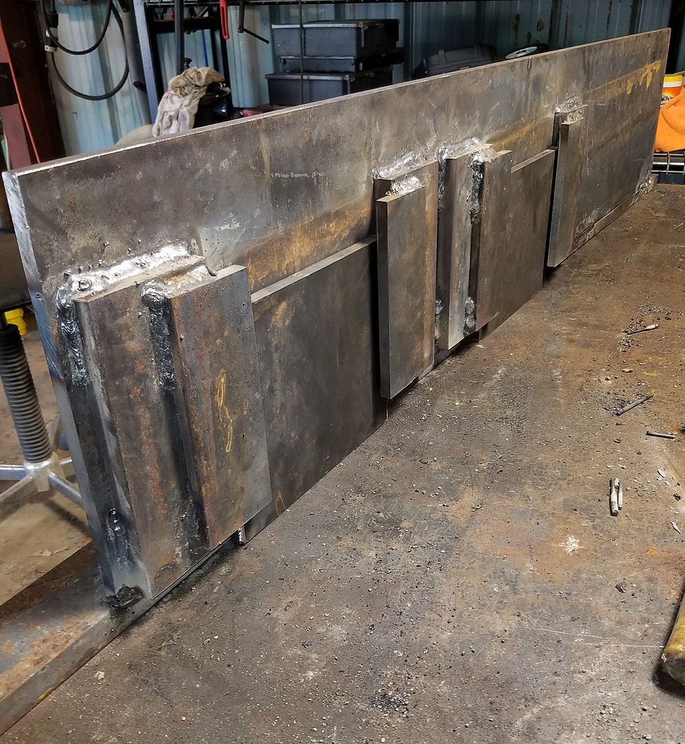
The had two materials I had for runners was 1/2" X 6" and 1" X 3". I went with the 1X3.
I figured there may be a time I will need the runners to "dig in", that would never happen with 6 inch wide runners.
The hope is that I will be able to move the two guillotine like plates up or down to adjust the grader blade height.
I say "HOPE", because it may be tricky welding the assembly together accurately enough that the plates do not bind.
The adjustment range will allow the blades to be positioned from one inch above the runners,
to several inches below the runners. Would I EVER want the blades to be higher than 1" above the runners??
My initial setting will have the blades even with the runners.
That seems to be typical of others land planes.
Next, I will weld in the three 84.5" tubes that space the sides apart.
Since the movable mounting plates are offset,
the the offset will cause the left front of the blade to be 22" back further than the right.
If my TRIG still works,, the grader blade will be at about a 15 degree angle,,
(84.5" wide,, 22" offset, is that ~15 degrees?)
The had two materials I had for runners was 1/2" X 6" and 1" X 3". I went with the 1X3.
I figured there may be a time I will need the runners to "dig in", that would never happen with 6 inch wide runners.
The hope is that I will be able to move the two guillotine like plates up or down to adjust the grader blade height.
I say "HOPE", because it may be tricky welding the assembly together accurately enough that the plates do not bind.
The adjustment range will allow the blades to be positioned from one inch above the runners,
to several inches below the runners. Would I EVER want the blades to be higher than 1" above the runners??
My initial setting will have the blades even with the runners.
That seems to be typical of others land planes.
Next, I will weld in the three 84.5" tubes that space the sides apart.
Rustyiron
Super Member
Would I EVER want the blades to be higher than 1" above the runners??
I made mine so that I could (hopefully) spread materials. It works pretty well, and so what if you don't use this feature. How do you plan on changing the depth? The pic. is from putting in a lawn & spreading topsoil at about 3". It moves from about a 1" cut to close to a 4" above "spreading" depth.
Attachments
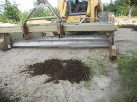
I made mine so that I could (hopefully) spread materials. It works pretty well, and so what if you don't use this feature. How do you plan on changing the depth? The pic. is from putting in a lawn & spreading topsoil at about 3". It moves from about a 1" cut to close to a 4" above "spreading" depth.
Very interesting!! :thumbsup:
I will see how high I can get the blade, I may run out of adjustment when the blades are 3" above the runners.
jwmorris
Veteran Member
- Joined
- Oct 3, 2007
- Messages
- 1,124
I punched the carriers for my blades and side plates for adjustment from 1/2" above grade to an inch and a half below (with rippers that can go negative 3" if needed).
I welded the angle iron that holds the blades at over 45 deg so I can backup to spread material without cutting, it pushes high down while riding on the skids.
Haven't moved them from 1/2" negative cutting forward yet.
I welded the angle iron that holds the blades at over 45 deg so I can backup to spread material without cutting, it pushes high down while riding on the skids.
Haven't moved them from 1/2" negative cutting forward yet.
jenkinsph
Super Star Member
You can pre drill to add 2x4 lumber or whatever to the skids to spread a layer of mulch or top soil. Just need a separate tractor/fel to keep the lpgs loaded with material as you move along.
Rustyiron
Super Member
That remindes me, I remember a landscapeing co. that put in lawns for the builders in a large subdivision. He bolted on long 7'-8' oak or locust 4x4's or so as skids to his regular box blade. This was 20 years ago and may have been the first so called "land plane" out there.:laughing: It did work well and at the time, I just wrote it off as hillbilly engineering.:confused3:
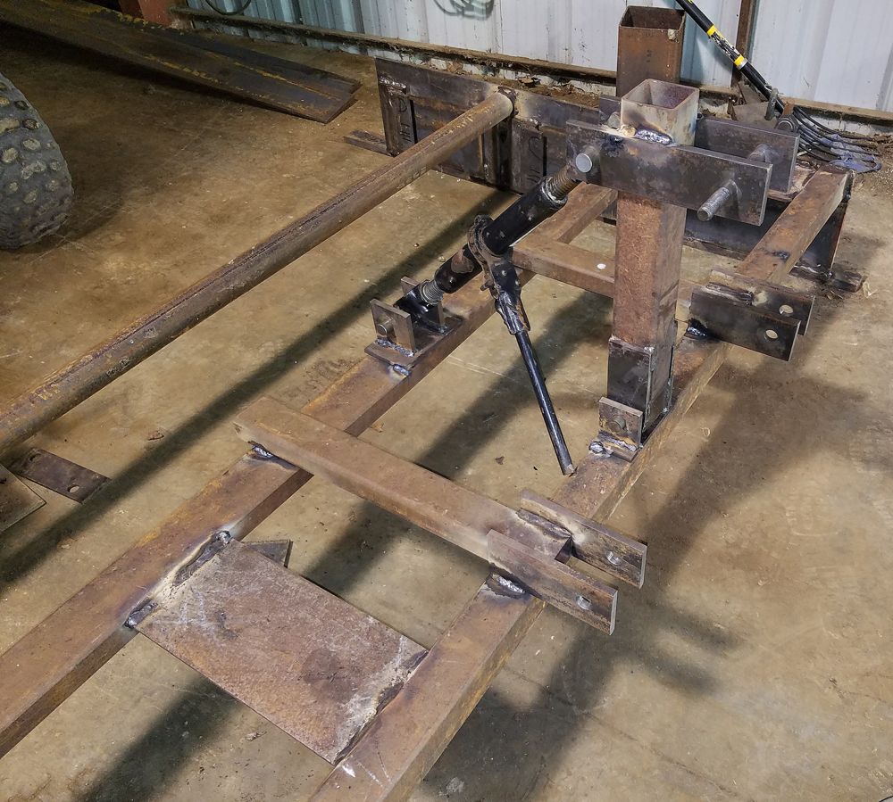
I was drilling the holes for the 3 point hitch attachment (one inch,, I could not find the 7/8" bit :laughing: )
and I took a pic.
I thought some of you might be wondering why I have a clamp permanently bolted to my drill press vise.

The clamp applies down pressure on the parts, when I am drilling multiple parts at one time.
Hot rolled steel varies enough in width, that the vise can not hold all the parts firmly.
The clamp insures that one or more of the parts do not start walking around.
The vise is a "self centering" type. That makes setup easier when you are drilling a bunch of holes in the center of a group of parts.
The drill will stay at the center of a part, whether it is 2, 3, 4, 6, etc inches wide,
both the front and rear vise jaws move as the handle is rotated.
and I took a pic.
I thought some of you might be wondering why I have a clamp permanently bolted to my drill press vise.
The clamp applies down pressure on the parts, when I am drilling multiple parts at one time.
Hot rolled steel varies enough in width, that the vise can not hold all the parts firmly.
The clamp insures that one or more of the parts do not start walking around.
The vise is a "self centering" type. That makes setup easier when you are drilling a bunch of holes in the center of a group of parts.
The drill will stay at the center of a part, whether it is 2, 3, 4, 6, etc inches wide,
both the front and rear vise jaws move as the handle is rotated.
jwmorris
Veteran Member
- Joined
- Oct 3, 2007
- Messages
- 1,124
Hot rolled steel varies enough in width, that the vise can not hold all the parts firmly.
Drop a strip of cardboard or wood between the moving jaw and parts. They will still be consistently spaced by the rear jaw and the strip will compress with the long ones and hold the shorter ones.
You can also run into the same issue in your saw. You can clamp them all together or if you have a welder handy tack the "drop" ends together so they don't move realitive to one another as they are fed.
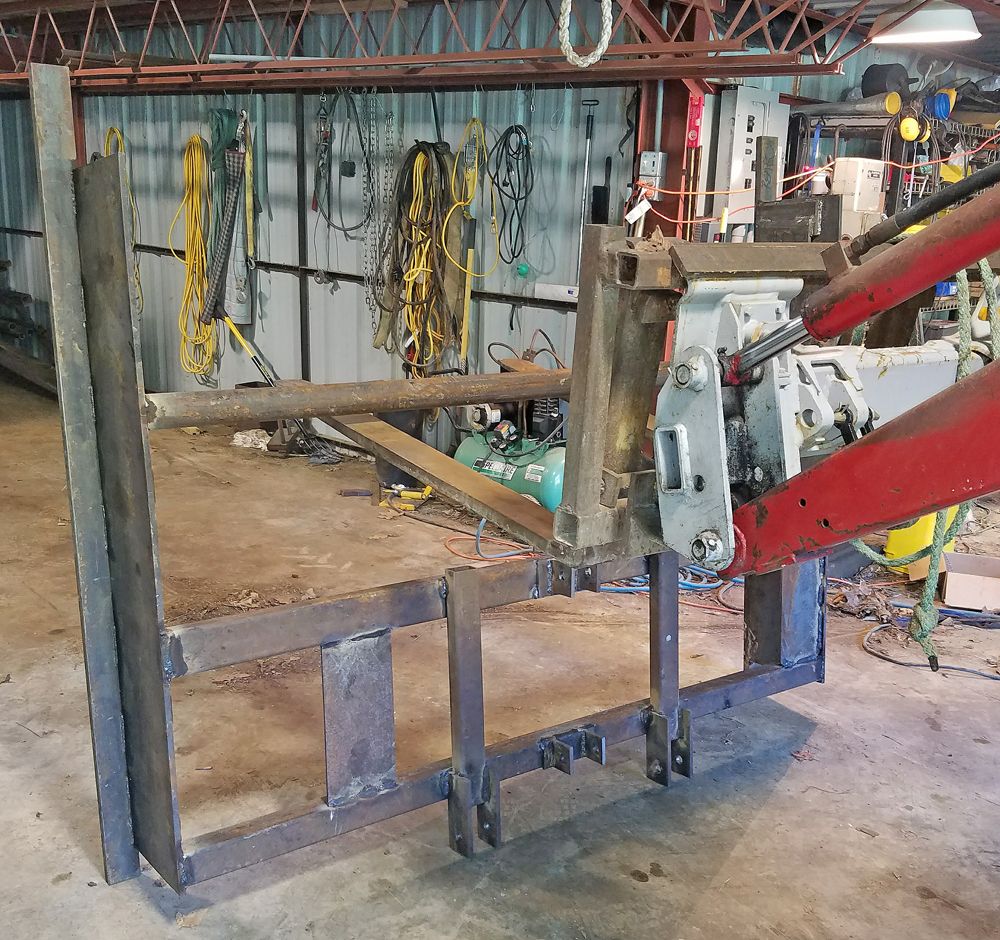
Last second design change,,,
I decided to add a bit of angle adjust-ability to the top link connection.
I can use the mechanical link shown, or a hydraulic cylinder,,,
I am trying to get all the welding done on the frame before I add the grader blades.
Hopefully, I will not have any distortion later that would inhibit the up and down movement of the grader blades.
