mjncad:
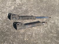
Actually, it's not either. The rods from the shocks measure 0.980", while the pins from Kubota measure 0.985" (25mm). The Kubota bushings are 1.015" or so, which gives about 0.020" of clearance. I bored out my bushings to fit those pins (so I can still use them on the loader arm ends).
The DOM tubing I have measures about 1.000" inside (how they do that reliably in a volume production, I don't know), so with the shock pins I would have 0.020" clearance. So, the clearance will be the same as the stock pins and bushings.
I'll have a problem with the
grapple cylinder, though. The cylinder ends have 1.020" bushings, so my 0.980" pins fit like socks on a goose. I have some 1" drill rod, but didn't want to deal with hardening it. I'm seriously considering using it for pins and leaving it unhardened. Anybody got any idea how hard the pins should be? I'm thinking that as long as they don't shear, they are hard enough. After all, the bushings aren't hardened.
Regards,
- Just Gary