Mini gantry crane

   / Mini gantry crane #1  

robstaples

Gold Member
Joined
Oct 13, 2013
Messages
355
Location
Near Ann Abor, Michigan
Tractor
kubota / L39 TLB, BX2680
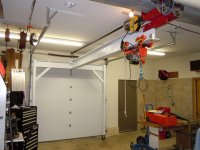
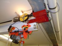
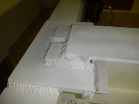
I thought I'd show my latest completed project- don't get many-. I have a 10x10 beam down the center of my building (colored gray in upper part of picture) I wanted to be able to move my MMM and snowblower and other things in and out of the garage door. Tractor takes it the rest of the way. Because of limited height, I needed to be able to move it out of the way of the door (L39 is tall). I used 4 trolleys, two 2 ton to ride on the steel beam and two 1 ton to carry the hoist on the 6x10 inch beam. All the white is aluminum so I could move it easier. The red dolly connector is steel. I took the ratchet out of the electrical cord spring-driven coilers so they take up the tension continuously.
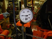
Rating: the winch is rated at 880 lb. My things to move are less than 700lbs. I was going to run a deflection test with a 2300 lb ironworker, but I thought why risk breaking things if I'm never going to lift that much. I followed the recent bridge crane thread and I know there is a safety limit risk.

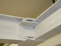
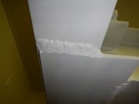
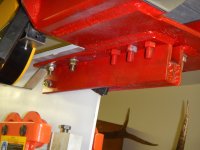
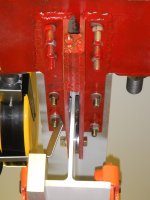
I designed it to rely on shear strength of 1" AL plate for the tee joint. The welds are respectable on top and bottom but the picture shows the tight quarters. I sound defensive, don't I. I've follow all the welding discussions on this forum. The L bracket is just to plug the pull strain on the tee joint. If it flexed too much, I'll add a 45 degree brace on each side. So far so good.
 

Attachments

  • DSCN3253 (2) (800x600).jpg
    DSCN3253 (2) (800x600).jpg
    237.9 KB · Views: 6,319
  • DSCN3254 (800x600).jpg
    DSCN3254 (800x600).jpg
    224.5 KB · Views: 1,107
  • DSCN3255 (800x600).jpg
    DSCN3255 (800x600).jpg
    161.4 KB · Views: 977
  • DSCN3256 (800x600).jpg
    DSCN3256 (800x600).jpg
    172.1 KB · Views: 1,769
  • DSCN3257 (800x600).jpg
    DSCN3257 (800x600).jpg
    198.5 KB · Views: 831
   / Mini gantry crane #2  
What's under the plywood on the floor?

Jim
 
   / Mini gantry crane #3  
Floor looks like concrete to me.

A lot of those welds look really cold too. What process did you use on the aluminum?
 
   / Mini gantry crane #4  
I beam looks like metal to me.
 
   / Mini gantry crane
  • Thread Starter
#5  
The floor is concrete stained with a few years of clumsiness. The aluminum was welded with a new Lincoln Power Wave C300 set at MIG with 3/64 wire set on pulsed mig. It would go to 300 amps but heat controlled by wire speed . The machine was more difficult to master than I had expected. And I haven't. And the push pull gun was a mistake for me to buy. The 25 ft length just pinched the wire when I was 10ft from my machine. Live and learn. The horizontal welds at my welding bench were better. I take a picture today of the better welds.
 
   / Mini gantry crane #6  
The welds do concern me. But I'll try not to be too critical.

Potential weak spots I see are
1. Welds
2. How you attached aluminum beam to red trolley
3. The legs. With a 800# load I bet they will flex alot when moving. Or are those just ment to.move the EMPTY hoist out of the way? What size and wall thickness are those legs.
4. Adding to 3, the casters. Any resistance in them muts more side load on the legs. Those look pretty small in diameter. Ever try to run a caster over a small piece of gravel?
 
   / Mini gantry crane #7  
Yeah man thats a cool idea, but those welds look suspect.
 
   / Mini gantry crane #8  
I'm trying to understand how this works.

Does the white uprights and white beam slide to the right or left enough to get the garage entrance completely clear?
 
   / Mini gantry crane
  • Thread Starter
#9  
Thanks for the interest and comments. The gantry moves left and right. To the right, it clears the door. To the left, further..25 total. My K. L39 is inside and the 10" beam clears the top of the roof but the trolleys don't. Your comments made me concerned to do a test. I tried to pick up my L39 to the limit of the electric hoist. I measured the height before and during the lift with a lift scale and a laser distance measurer. The lift maxed at 1000lb ( hydraulic scale accuracy ?? 0-5000lb). The center of the tee dropped 1/32" and the legs, on the casters, spread 1/8". seems ok.
Material used:
The legs are 3"x6"x1/4". 45s are 3x3x1/4". The H beam base of the tee is 10"x 6 and the cross is 8"x5?

The top and bottom welds were done at a bench. Better than the in place vertical welds.

The AL and steel(red) at jointed by 4 vertical grade 8 bolts 1/2 " and one web bolt.

The left right movement with load will need a freshly swept floor near the wheels and a decision based on what I'm trying to move. I thought I could temporarily brace the legs near the wheels together rigidly if it's heavy like my metal lathe
 

Attachments

  • DSCN5307 (800x600).jpg
    DSCN5307 (800x600).jpg
    185.9 KB · Views: 542
  • DSCN5309 (800x600).jpg
    DSCN5309 (800x600).jpg
    166.2 KB · Views: 448
  • DSCN5311 (800x600).jpg
    DSCN5311 (800x600).jpg
    263.9 KB · Views: 460
  • DSCN5312 (600x800).jpg
    DSCN5312 (600x800).jpg
    254.6 KB · Views: 534
  • DSCN5313 (800x600).jpg
    DSCN5313 (800x600).jpg
    269.9 KB · Views: 507
 
Top