boggen
Elite Member
- Joined
- Feb 22, 2011
- Messages
- 3,829
- Location
- Trivoli, IL
- Tractor
- SSTT (Sideways Snake Tain Tractor) and STB (sideways train box) tractor, dirt harvester
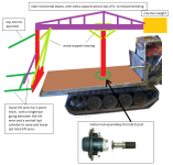
quick diagram, for single joystick control for steering. i had to draw it out to figure out what you were saying.

your notation of 3pt hitch, idea of free standing cranes came to mind, for main beam, and then counter weight on opposite end. be interesting if you could adjust distance of were weight was on the fly with wireless remote, or perhaps pulling a pin and sliding a pipe in and out to adjust counter weight position for an implement. further counter weight was away from main center pole more counter balance weight it would achieve. closer the counter weight was to main center pole less counter balance weight it would produce.
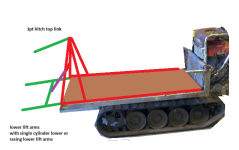
single cylinder to raise / lower lower lift arms on 3pt hitch. no way to adjust "angle" or "tilt" when thinking of TNT (top & tilt) for a 3pt hitch. perhaps if you went with 2 individual cylinders 1 for each lift arm. you could have TNT.

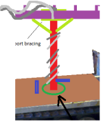
if you go with 360 spin. how are you going to keep from tangling the hyd hoses? and pinching them and tearing them apart?
will there be a "stop" be welded to the tracked buggy frame. and then a "tab" welded to the shaft extending upwards. so you only get 359 degree spin. and not a fully 360 degree spin?

or going to something more complex. like you might find on a tracked excavator. were you can keep spinning around and around and around while the tracks stay put?
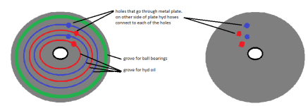
instead of the trailer hub, below diagram. was more along thoughts of 2 thicker metal plates. were bottom plate attached to tracked buggy and top plate (mirror copy of bottom plate just flipped upside down) attached to main pole that went upwards. the top plate would spin freely over bottom plate. and the groves would allow hyd oil to pass through the plates. regardless of spinning.

or are you going to skip the 360 turn completely for the center pole..(like your current tracked robot) and go for a more simpler design? and if you get into tight spot, just raise 3pt hitch implement and then cause one track to reverse while other track goes forward?


your notation of 3pt hitch, idea of free standing cranes came to mind, for main beam, and then counter weight on opposite end. be interesting if you could adjust distance of were weight was on the fly with wireless remote, or perhaps pulling a pin and sliding a pipe in and out to adjust counter weight position for an implement. further counter weight was away from main center pole more counter balance weight it would achieve. closer the counter weight was to main center pole less counter balance weight it would produce.
single cylinder to raise / lower lower lift arms on 3pt hitch. no way to adjust "angle" or "tilt" when thinking of TNT (top & tilt) for a 3pt hitch. perhaps if you went with 2 individual cylinders 1 for each lift arm. you could have TNT.

if you go with 360 spin. how are you going to keep from tangling the hyd hoses? and pinching them and tearing them apart?
will there be a "stop" be welded to the tracked buggy frame. and then a "tab" welded to the shaft extending upwards. so you only get 359 degree spin. and not a fully 360 degree spin?

or going to something more complex. like you might find on a tracked excavator. were you can keep spinning around and around and around while the tracks stay put?
instead of the trailer hub, below diagram. was more along thoughts of 2 thicker metal plates. were bottom plate attached to tracked buggy and top plate (mirror copy of bottom plate just flipped upside down) attached to main pole that went upwards. the top plate would spin freely over bottom plate. and the groves would allow hyd oil to pass through the plates. regardless of spinning.

or are you going to skip the 360 turn completely for the center pole..(like your current tracked robot) and go for a more simpler design? and if you get into tight spot, just raise 3pt hitch implement and then cause one track to reverse while other track goes forward?
