DiskDoctr
Platinum Member
Mine is connected like that and it does the same exact thing. You can feel the detent for the bucket curl, but if you push it too fast for lowering the the whole loader, it flies up in the opposite direction and shakes the whole tractor. I have been dealing with it by being very careful while lowering. But it is a pain. I could post a video when its not raining.
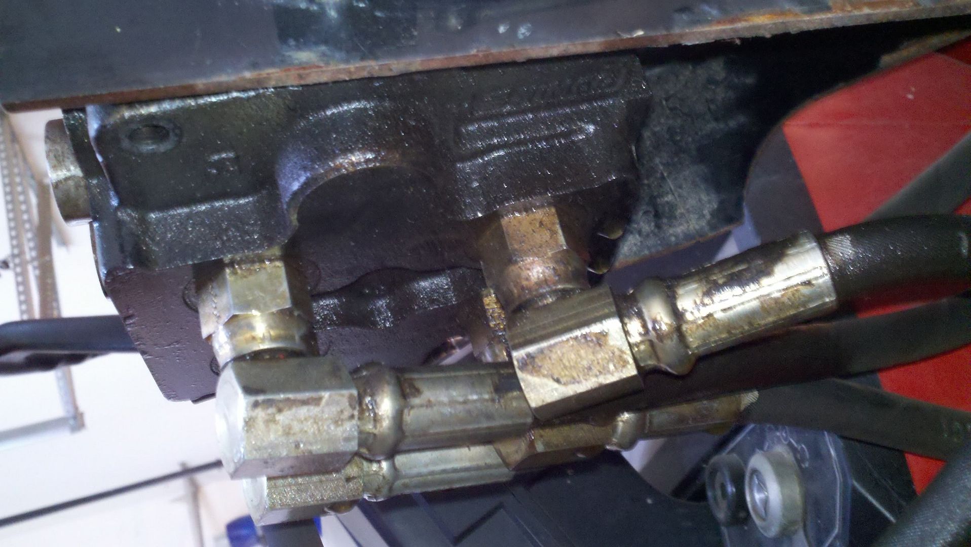
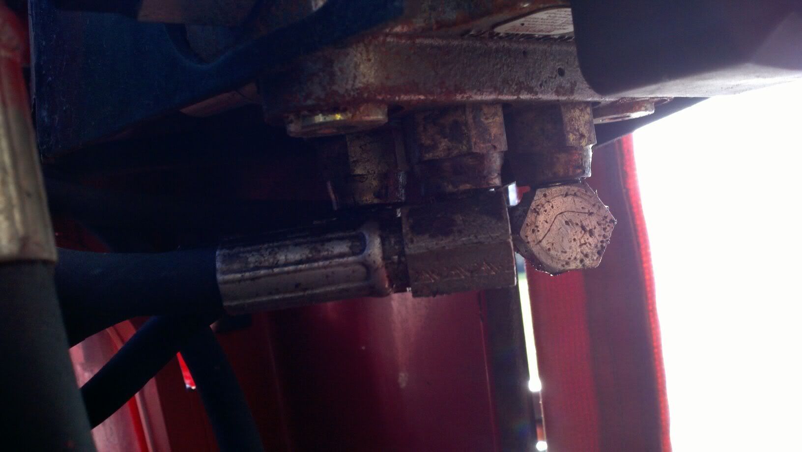
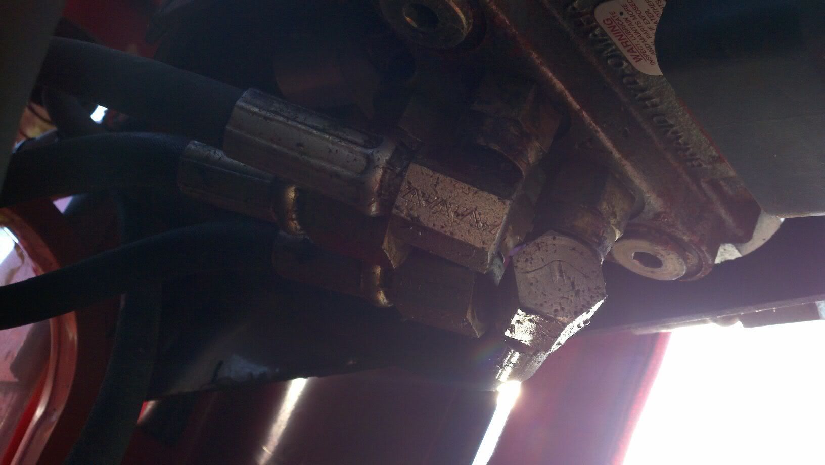
Is your joystick sloppy or sticking? The Nimco valve on my tractor had a mechanical failure of the pivot point. This allowed the valve to actuate valves in a non-standard way.
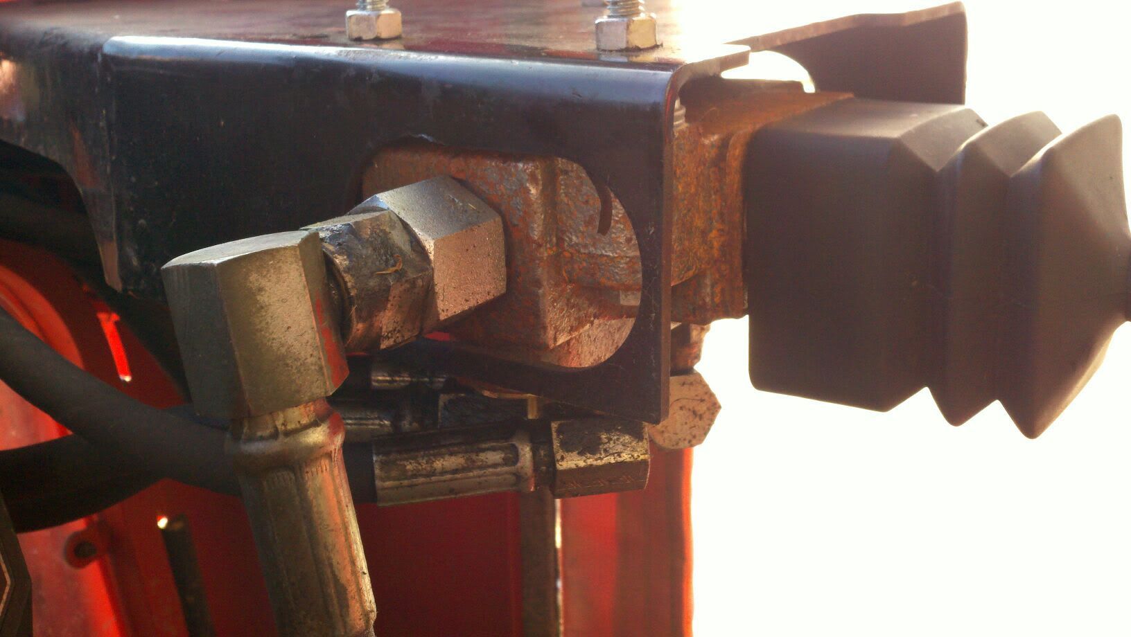
Specifically, if I pushed too far forward, the loader would initially work as expected, but when the pivot point would lift out of place a bit, the rear valves would be pulled up farther than it was supposed to.
I think this somehow interfered with the normal flow of the circuits, causing a rapid reversal of the cylinder.
I'm sure others can explain this better.
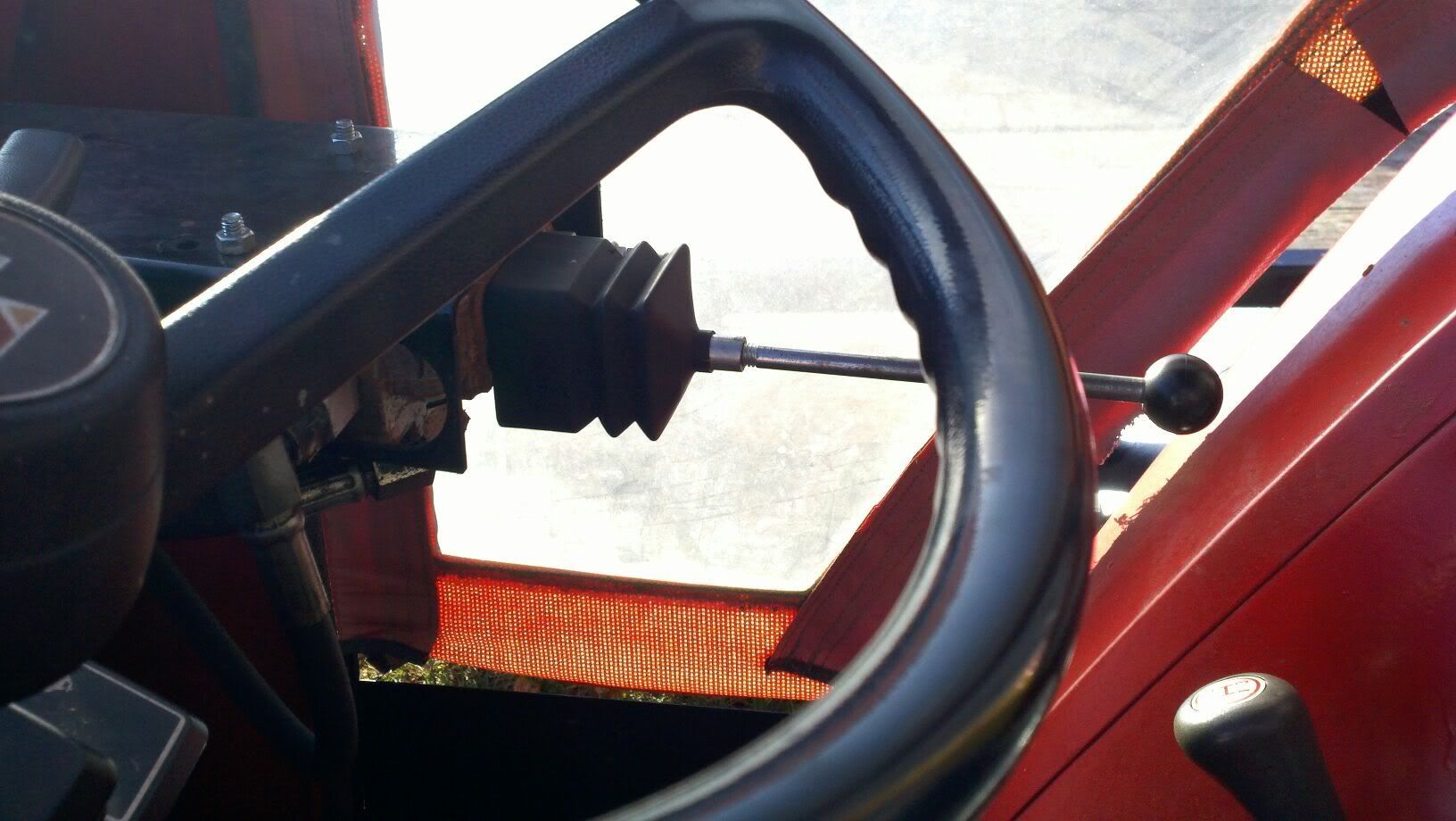
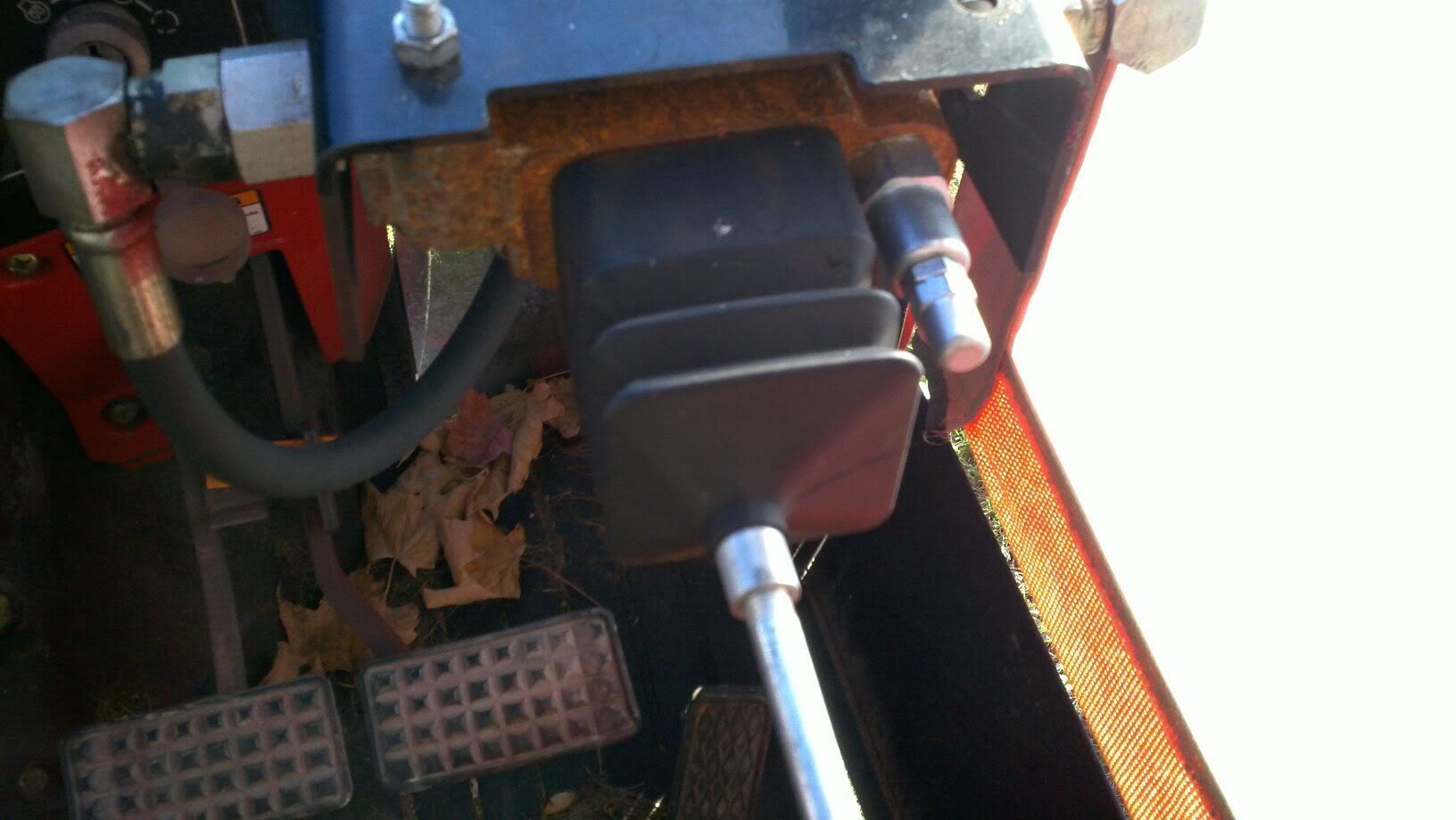
You can try pushing the base of the joystick against the valve assembly and take note if it feels like it is slipping or lifting out of place. May feel a resistance (may feel like a detent), hear a clicking noise, or the valve may seem overly stiff or floppy.
If so, pull the boot up off the valve with the bucket fully down and the tractor off. Move the valve around and watch for any parts coming out of place. Make sure the joystick components pivot smoothly and completely.
Hope this helps!
- JC