You are using an out of date browser. It may not display this or other websites correctly.
You should upgrade or use an alternative browser.
You should upgrade or use an alternative browser.
Questions about radiant heat system
- Thread starter mx842
- Start date
- Views: 29928
More options
Who Replied?
/ Questions about radiant heat system
#81
") )
)
OP
mx842
Platinum Member
- Joined
- Feb 26, 2011
- Messages
- 878
- Location
- Richmond Va
- Tractor
- Kubota L3301, PowerKing 2414, John Deere 316, Gravely ZT HD 52
You know what?????? This isn't fun anymore. Well maybe still a little but this thing is driving me nuts. I spent all day yesterday and until 4:30 this morning re-plumbing the manifold pump and a few other things at the manifold and I still cant get those flow meters to show anything. The little red disk is stuck right at the top and won't move. I took a couple of the flow meters apart and cleaned them looking for something that wasn't there. Put it all back together and still the same. I've back flushed, front flushed, sideways flushed and it still seems to have air somewhere. I changed the way I had the pump plumbed and it seems like it was a little better but there is noise in the lines like water trickling down a little brook then I notice the pressure needle going up and down 3 or 4 lbs and the noise seems consistant with the pressure movement. I know there is some flow going through the loops because I can take the loop end off at the return manifold and there is water flowing but it just wont move the meter. I'm about ready to pull all that mess out and buy and new manifold.
When I bought the manifold they didn't have a 8 loop one so I had to get a 5 and a 4 loop one and connect them together. I was pouring the floor so I had to do something. I don't know if that may be part of the problem but the guys at pex universe said it should work fine. I don't know, I guess I'll leave it for awhile and hope it works itself out.
When I bought the manifold they didn't have a 8 loop one so I had to get a 5 and a 4 loop one and connect them together. I was pouring the floor so I had to do something. I don't know if that may be part of the problem but the guys at pex universe said it should work fine. I don't know, I guess I'll leave it for awhile and hope it works itself out.
CalG
Super Member
- Joined
- Sep 29, 2011
- Messages
- 9,193
- Location
- vermont
- Tractor
- Hurlimann 435, Fordson E27n, Bolens HT-23, Kubota B7200, Kubota B2601
You know what?????? This isn't fun anymore. Well maybe still a little but this thing is driving me nuts. I spent all day yesterday and until 4:30 this morning re-plumbing the manifold pump and a few other things at the manifold and I still cant get those flow meters to show anything. The little red disk is stuck right at the top and won't move. I took a couple of the flow meters apart and cleaned them looking for something that wasn't there. Put it all back together and still the same. I've back flushed, front flushed, sideways flushed and it still seems to have air somewhere. I changed the way I had the pump plumbed and it seems like it was a little better but there is noise in the lines like water trickling down a little brook then I notice the pressure needle going up and down 3 or 4 lbs and the noise seems consistant with the pressure movement. I know there is some flow going through the loops because I can take the loop end off at the return manifold and there is water flowing but it just wont move the meter. I'm about ready to pull all that mess out and buy and new manifold.
When I bought the manifold they didn't have a 8 loop one so I had to get a 5 and a 4 loop one and connect them together. I was pouring the floor so I had to do something. I don't know if that may be part of the problem but the guys at pex universe said it should work fine. I don't know, I guess I'll leave it for awhile and hope it works itself out.
Quit dick'n around with the entire manifold and multi circuit loops. Get ONE LOOP to work, then move to more complication.
There must be something, some detail you are missing.
Raspy
Veteran Member
- Joined
- Dec 16, 2006
- Messages
- 1,656
- Location
- Smith Valley, Nevada
- Tractor
- NH TC29DA, F250 Tremor, Jeep Rubicon
Maybe you could take a few pix and post them of the setup you have. The noise you describe sounds like surging air. It can be frustrating at times.
quicksandfarmer
Elite Member
Quit dick'n around with the entire manifold and multi circuit loops. Get ONE LOOP to work, then move to more complication.
There must be something, some detail you are missing.
This. Divide and conquer. Break it into the smallest possible units, if possible things you can assess visually. I'd cut out the circulator pump and hook it up to house water and see if you can get flow through.
OP
mx842
Platinum Member
- Joined
- Feb 26, 2011
- Messages
- 878
- Location
- Richmond Va
- Tractor
- Kubota L3301, PowerKing 2414, John Deere 316, Gravely ZT HD 52
Quit dick'n around with the entire manifold and multi circuit loops. Get ONE LOOP to work, then move to more complication.
There must be something, some detail you are missing.
I'm not sure what you mean by multi circuit loops. I can shut off every loop but one......any one and the flow meter still doesn't move. I know there is water going through them just don't know how much.
OP
mx842
Platinum Member
- Joined
- Feb 26, 2011
- Messages
- 878
- Location
- Richmond Va
- Tractor
- Kubota L3301, PowerKing 2414, John Deere 316, Gravely ZT HD 52
mx,
Regarding plumbing the HX to the water heater: The HX is horizontal and it doesn't matter which line is in or out, but plumb the out to the top of the tank with as little restriction as possible and an up-slope all the way. This will help the thermosyphon affect and, during a power failure, will circulate some water. Assist it with a pump to get the maximum BTUs to your tank. The 007 should be fine for this duty. Use the 3/4" port on the side of the tank near the top, typically, this is the pressure relief port, as the return from the HX.
TEE the output to your floor pump at the same upper side outlet of the tank, where the HX line ties in. Simply screw a brass or galvy tee on a short nipple sticking out of the tank fitting and plumb each line to it. Return the floor loop to the cold inlet on top of the tank. Pull the dip tube out of the cold inlet fitting and set it aside. Put an automatic air vent on the hot outlet. If you insist on an auto fill system, tie it in at the cold tank inlet with another tee.
I suppose the best flow pattern would be to place the HX pump on the bottom line pumping away from the tank toward the HX. Place the floor on the line from the upper side fitting tee, pumping toward the floor. Return it to the cold top fitting as mentioned.
All of this will tend to move air to the tank and get it out of the system. It will not inhibit thermosyphon.
Install tees on the supply and return lines to the floor. One just before the pump, which is pumping toward the manifold. And one after the manifold on the return line to the tank. Connect these with a 3/4 pipe and a ball valve. This will allow you to throttle a bypass and control the supply temperature somewhat. It also reduces restriction in the floor loop. You'll still get all the available energy to the floor, but you'll avoid scalding temperatures and you'll help the pump purge the air. A bit of manual adjusting of this ball valve will get you find the right setting. Probably 1/2 open for starters.
Install a ball valve on the return line to the tank from the floor. Preferably, near the tank. Then tee in a hose bib right before this valve (on the manifold side). You can then close the valve and open the bib to manually purge the floor loops. This will help you get it all started and force out any air.
Again, look carefully at the manifold to make sure you have the loop restrictors fully open. Very important.
I went back and looked at this again and am a little cornfused :confused2: I installed a tee just before the isolation valve going into the tank. Is that to let water in or out of the system? If out, where would you dump new water into the system to get the most air out while purging?
OP
mx842
Platinum Member
- Joined
- Feb 26, 2011
- Messages
- 878
- Location
- Richmond Va
- Tractor
- Kubota L3301, PowerKing 2414, John Deere 316, Gravely ZT HD 52
Also I added tees between the supply and return with a valve in the middle. That seems to be working as you described. The only thing is I didn't have room to put a tee before the pump not enough pipe coming out the wall so I had to put a tee after the pump about 10" before it enters the manifold. Space is tight in that area by design. I mean this is a small office area and I wanted to be able to have all this equipment in the wall with a sliding door that would cover this mess up and also keep it protected from inquisitive hands and other traffic in the area. I guess I could have done the same thing over in the boiler room and would have had more room to work. I want to re-run the way I have the manifold return line plumbed into the tank anyway. Would I get the same effect putting the tees in the boiler room as at the manifold?
Right now I have the manifold return water entering into the tank at the bottom drain port. As I mentioned before somewhere the way that side is plumbed now is manifold return teed into the bottom with a drain valve out the straight part of the tee. Supply to the manifolds (1" port ) where the upper heating element was. The return to the HX I have coming out the lower 1" heating element port. And the supply from the HX to the tank goes into the top 3/4" port where the T&P valve was. I didn't have room the way my setup is to pump into the HX so it's on the return to the tank out of the HX. The aqua stat I put in to control the 007E pump works great for the time being I have it set to turn the little pump on at 160 and it goes off at 140. I have another aqua stat I want to put on the line right where it comes out of the 1" supply port at the tank set at around 110 to turn on the circulator at the manifold. If this works out I want to get another aqua stat with a differential lever on it so that pump can run longer. I haven't run the wires over to the manifold yet for this to work but will do so soon, I just want to see how this aqua stat I have works before I do buy another one.
I was wondering if I could use the old oil burner and circulator control I have to do both. Say use the burner side to cut on the 007 and the circulator part to cut on the bigger pump? It's just a thought I was kicking around.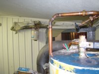
Raspy
Veteran Member
- Joined
- Dec 16, 2006
- Messages
- 1,656
- Location
- Smith Valley, Nevada
- Tractor
- NH TC29DA, F250 Tremor, Jeep Rubicon
For some reason, we still haven't solved the basic problem of getting the air out and getting good flow through the loops.
Your system looks like a figure 8 with the tank as the center of the 8. It is the X part of the 8. If you simply valve off one side of that 8, the manifold side, on both sup and ret lines, then add tees next to the valves, you can flush that side of the 8. Flush both pipes, the pump, the manifold and the loops all at once.
Remember, the center of the figure 8 is an X, That is where the tank is. It's the X. The supply line comes from the X and goes to a valve, then a tee (tee 1) then the pump and then the manifold, then the return line comes from the manifold back to another tee (tee 2) then another valve and back to the X (tank). Both tees have hose bibs, or tee 1 has the auto fill instead. The flow goes toward the manifold hot side, or red side. I don't know if your flow meters are on the supply or return (hot or cold) side. Watts manifolds have them on the hot or supply side.
Now, fill the system (manifold side of the X) at tee 1 with your auto fill. Then close both valves and open tee 2 hose bib to purge the air out of the pipes, the manifold, the loops and the pump. Done.
Or, with no auto fill, connect a hose to tee 1 with a bib instead of the fill valve and use city pressure to blast the system out. Auto fill is better.
Now, open the valves, close the bibs on the tees and start the pump. System pressure should be at 10 to 20 PSI to begin. Static cool pressure later should be set a 12. If air gets into the pump again, open tee 2 hose bib while it's running to force the air through the pump. You can close the supply valve with the pump running to help with this process, if needed. With no air, and the loop restrictors open, and the flow in the right direction, you should be seeing about 1 gpm at each flow meter and the pump will be quiet.
Maybe your flow meters are simply stuck and you are getting flow. Could be. With everything running and most of the air out, slowly close valve 1, before the pump, and listen to the pump as you do. Does it's sound change? If so it's probably pumping. If it's pumping you have flow in the loops. It's sound may change with pockets of bubbles going through it during the startup process. Listen for this. A grinding sound that will come and go. That's good. It means it's working. Once it's working it will clear itself completely over time and become silent. It's performance will also increase and you'll see a higher flow rate. A steady grinding sound probably means it's air locked and you should open bib 2, close valve 1, to clear it or help it. Just fiddle with it
and look for sound or visual changes. Give it some time to get things sorted out. Adjust the pressure to make the bubbles smaller if needed. You can even glance at it with a wary eye to let it know your watching. You might have to come up with some new words in the process, but it's only air, water, gravity, pressure, a few valves and a centrifugal pump. What could possibly go wrong?
Put a similar set of valves and tees on the other side of the X to fill and purge the heat exchanger side if needed (I'm not sure you do need them there).
Fill the tank. You can close valve 1, open valve 2 and let the auto fill purge the system by sending all air and water to the tank through the manifold and return line. Then the auto-vent you installed on top of the tank will vent the air. Meanwhile, your thermosyphon lines from the heat exchanger, that slope upwards, should let air trickle up to the tank and get out. In theory, you should be able to just fill it up and turn it on. The heat exchanger pump, if in the right place, may purge during the process and need no further help.
Now get that thing going so we can see how much energy it can transfer.
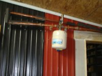
Install your expansion tank somewhere. It might be best on the top of the tank or on tee 1. You could put a second tee on the line running from your auto-fill to tee 1 and screw it on there. It also can be remote mounted but tied in at that point. That would put it on the suction side of the manifold pump which would tend to make the bubbles smaller in the manifold and make the pump deal with less air.
Your system looks like a figure 8 with the tank as the center of the 8. It is the X part of the 8. If you simply valve off one side of that 8, the manifold side, on both sup and ret lines, then add tees next to the valves, you can flush that side of the 8. Flush both pipes, the pump, the manifold and the loops all at once.
Remember, the center of the figure 8 is an X, That is where the tank is. It's the X. The supply line comes from the X and goes to a valve, then a tee (tee 1) then the pump and then the manifold, then the return line comes from the manifold back to another tee (tee 2) then another valve and back to the X (tank). Both tees have hose bibs, or tee 1 has the auto fill instead. The flow goes toward the manifold hot side, or red side. I don't know if your flow meters are on the supply or return (hot or cold) side. Watts manifolds have them on the hot or supply side.
Now, fill the system (manifold side of the X) at tee 1 with your auto fill. Then close both valves and open tee 2 hose bib to purge the air out of the pipes, the manifold, the loops and the pump. Done.
Or, with no auto fill, connect a hose to tee 1 with a bib instead of the fill valve and use city pressure to blast the system out. Auto fill is better.
Now, open the valves, close the bibs on the tees and start the pump. System pressure should be at 10 to 20 PSI to begin. Static cool pressure later should be set a 12. If air gets into the pump again, open tee 2 hose bib while it's running to force the air through the pump. You can close the supply valve with the pump running to help with this process, if needed. With no air, and the loop restrictors open, and the flow in the right direction, you should be seeing about 1 gpm at each flow meter and the pump will be quiet.
Maybe your flow meters are simply stuck and you are getting flow. Could be. With everything running and most of the air out, slowly close valve 1, before the pump, and listen to the pump as you do. Does it's sound change? If so it's probably pumping. If it's pumping you have flow in the loops. It's sound may change with pockets of bubbles going through it during the startup process. Listen for this. A grinding sound that will come and go. That's good. It means it's working. Once it's working it will clear itself completely over time and become silent. It's performance will also increase and you'll see a higher flow rate. A steady grinding sound probably means it's air locked and you should open bib 2, close valve 1, to clear it or help it. Just fiddle with it
and look for sound or visual changes. Give it some time to get things sorted out. Adjust the pressure to make the bubbles smaller if needed. You can even glance at it with a wary eye to let it know your watching. You might have to come up with some new words in the process, but it's only air, water, gravity, pressure, a few valves and a centrifugal pump. What could possibly go wrong?
Put a similar set of valves and tees on the other side of the X to fill and purge the heat exchanger side if needed (I'm not sure you do need them there).
Fill the tank. You can close valve 1, open valve 2 and let the auto fill purge the system by sending all air and water to the tank through the manifold and return line. Then the auto-vent you installed on top of the tank will vent the air. Meanwhile, your thermosyphon lines from the heat exchanger, that slope upwards, should let air trickle up to the tank and get out. In theory, you should be able to just fill it up and turn it on. The heat exchanger pump, if in the right place, may purge during the process and need no further help.
Now get that thing going so we can see how much energy it can transfer.
Install your expansion tank somewhere. It might be best on the top of the tank or on tee 1. You could put a second tee on the line running from your auto-fill to tee 1 and screw it on there. It also can be remote mounted but tied in at that point. That would put it on the suction side of the manifold pump which would tend to make the bubbles smaller in the manifold and make the pump deal with less air.
Raspy
Veteran Member
- Joined
- Dec 16, 2006
- Messages
- 1,656
- Location
- Smith Valley, Nevada
- Tractor
- NH TC29DA, F250 Tremor, Jeep Rubicon
You might be able to use the old burner control, as you mentioned. But be sure it is designed for line voltage on both outputs. Sometimes you can jumper the relay power supply terminals to power them with line voltage. From the factory, they might be set up to control a 24v circuit. Not sure why you need that control anyway as you cannot turn the heat exchanger pump off just because the room has gotten warm enough to turn off the thermostat. No room thermostat should be used here or you'll have run-away temps in the HX.
Your aquastat logic seem OK to me. Just be sure the bulbs are in the right places to sense the heat under any circumstances. I don't know why you need an additional controller. Just power the aquastats and they will turn on whenever there is heat. A simple wall switch that feeds them and provides a service disconnect should be fine. Since they are doing two separate jobs their run times will overlap but not start or stop at the same time. That's fine. I guess the only reason you even need two of them is to regulate the heat exchanger temperature more accurately and keep it hot to keep soot down. But I'm not sure that will make much difference. There is a lot to learn here.
Your aquastat logic seem OK to me. Just be sure the bulbs are in the right places to sense the heat under any circumstances. I don't know why you need an additional controller. Just power the aquastats and they will turn on whenever there is heat. A simple wall switch that feeds them and provides a service disconnect should be fine. Since they are doing two separate jobs their run times will overlap but not start or stop at the same time. That's fine. I guess the only reason you even need two of them is to regulate the heat exchanger temperature more accurately and keep it hot to keep soot down. But I'm not sure that will make much difference. There is a lot to learn here.
OP
mx842
Platinum Member
- Joined
- Feb 26, 2011
- Messages
- 878
- Location
- Richmond Va
- Tractor
- Kubota L3301, PowerKing 2414, John Deere 316, Gravely ZT HD 52
You might be able to use the old burner control, as you mentioned. But be sure it is designed for line voltage on both outputs. Sometimes you can jumper the relay power supply terminals to power them with line voltage. From the factory, they might be set up to control a 24v circuit. Not sure why you need that control anyway as you cannot turn the heat exchanger pump off just because the room has gotten warm enough to turn off the thermostat. No room thermostat should be used here or you'll have run-away temps in the HX.
Your aquastat logic seem OK to me. Just be sure the bulbs are in the right places to sense the heat under any circumstances. I don't know why you need an additional controller. Just power the aquastats and they will turn on whenever there is heat. A simple wall switch that feeds them and provides a service disconnect should be fine. Since they are doing two separate jobs their run times will overlap but not start or stop at the same time. That's fine. I guess the only reason you even need two of them is to regulate the heat exchanger temperature more accurately and keep it hot to keep soot down. But I'm not sure that will make much difference. There is a lot to learn here.
Did everyone get through turkey day alright? I ate so much yesterday that I felt so full I couldn't take my usual after dinner nap and decided to go out and split wood for a couple hours and to work through it. The only problem with that was once I worked it off I was hungry again and had to eat one of the chocolate pies my wife made for the crowd we had over. It's amazing what a chocolate pie and a couple bud lite's will do to induce nap time.:licking:
The last post you made made it clearer as to what you were saying and now I know what you were talking about with regard to filling and purging the supply and return lines from the manifolds. I need to add another tee on the supply side to the loops for another hose bib. Before I was trying to fill the system by closing valve number 2 and opening hose bib number two then adding water through the hose bib on the bottom of the tank. I was having problems there because the T&P valve on the HX kept popping off, not letting me purge the manifold side completely. I tried it several ways with little success and today I plan on fixing that with adding that other tee and hose bib. The funny thing is I had that setup the way I had piped it the first time before I re-piped it the third time.:laughing:
Oh I wasn't planning on using that burner control I was just wondering if it would work. But the circulator and burner terminals are set up for line voltage. It does have a relay that switches to 24v but that is for the thermostat side of the control. When I was thinking about trying to use this control I was thinking about using an aqua stat rather than a thermostat to operate the control. Then I found this other high limit aqua stat I had on a shelf and decided to use it instead. I run into this a lot when I am doing projects using pieces and parts that I have on hand.
I have the aqua stat on the HX about dialed in. It cuts on the HX pump to the tank at 160 and off at 140. I've been watching it for a couple days now through many cycles and it seems pretty consistant. I may have to bump it up to around 180/160 once I get the wire run for the other pump and aqua stat for the loops on the other side but we'll see how it goes once I get this other tee installed so I can get the air out. It's been running a couple days now and I can tell that it has gotten rid of a lot of the air by itself. The pump sounds happier but I can still hear water rattling around the manifold supply lines at times. Oh and that 3/4 line I added between the supply and return at the manifold seems to be working nicely as I can feel it mixing the hot water with the colder return water by feeling the return pipe. Thanks for taking time to help me work this out. I took some pics yesterday when I was out in the shop but I have been too lazy to go back out there to get my camera so I can post them this morning. Hopefully I'll get over that half a chocolate pie I ate for breakfast this morning so I can get going soon because I still have two and a half pies to go before they are all gone. :dance1:
Raspy
Veteran Member
- Joined
- Dec 16, 2006
- Messages
- 1,656
- Location
- Smith Valley, Nevada
- Tractor
- NH TC29DA, F250 Tremor, Jeep Rubicon
mx,
Sounds like you're just about there. Good news.
I like aquastats and I'm assuming you're using the old ones with the bulb and the mechanical switch. They are extremely reliable. I have a number of them sitting around and like to use them in cases like yours. I'm also happy tour bypass is working as needed.
Since your setup is operating and clearing itself over time, maybe you don't need to cut into it again to install the purging tee. At least not now. That point was where I also thought it would be nice to install the fill regulator, so where did you end up putting that and the expansion tank?
What are the flow meters reading? Are you getting noticeable heat in the floor?
I hope you can tear yourself away from the chocolate pie long enough to send some pix and give a performance report! :laughing:
OP
mx842
Platinum Member
- Joined
- Feb 26, 2011
- Messages
- 878
- Location
- Richmond Va
- Tractor
- Kubota L3301, PowerKing 2414, John Deere 316, Gravely ZT HD 52
mx,
Sounds like you're just about there. Good news.
I like aquastats and I'm assuming you're using the old ones with the bulb and the mechanical switch. They are extremely reliable. I have a number of them sitting around and like to use them in cases like yours. I'm also happy tour bypass is working as needed.
Since your setup is operating and clearing itself over time, maybe you don't need to cut into it again to install the purging tee. At least not now. That point was where I also thought it would be nice to install the fill regulator, so where did you end up putting that and the expansion tank?
What are the flow meters reading? Are you getting noticeable heat in the floor?
I hope you can tear yourself away from the chocolate pie long enough to send some pix and give a performance report! :laughing:
I haven't been burning too hard the past couple days it's been pretty warm and the chocolate pie has been holding out pretty good. Yesterday I spent the day running a wire from the manifold room to the boiler room. Hopefully I will get it all hooked up today and working. I still can't see any movement with the little red disk in the flow meters but there has to be some flow. I'm still going to add that tee and hose bib because it wont be too much trouble doing it. There is still some air floating around so it might help to install that tee and bib so I can purge the system again......it can't hurt I don't guess.
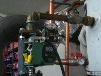
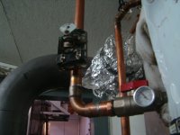
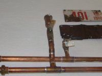
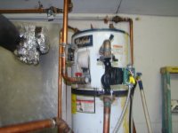
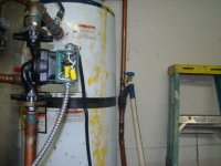
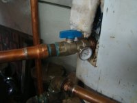
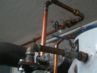
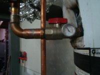
Here are some new pics I took yesterday hopefully you can tell whats going on.
Attachments
-
 007e pump.JPG107.7 KB · Views: 143
 -
 aqua stat for manifold pump.JPG112.4 KB · Views: 141
 -
 air valve at higest point in system.JPG100.9 KB · Views: 140
 -
 bottom of tank.JPG104.8 KB · Views: 154
 -
 DSC03708.JPG96.5 KB · Views: 127
 -
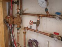 manifold pump piping.JPG111.4 KB · Views: 157
 -
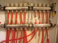 manifold setup.JPG91.8 KB · Views: 147
 -
 manual airor fill valve.JPG122.1 KB · Views: 140
OP
mx842
Platinum Member
- Joined
- Feb 26, 2011
- Messages
- 878
- Location
- Richmond Va
- Tractor
- Kubota L3301, PowerKing 2414, John Deere 316, Gravely ZT HD 52
Raspy
Veteran Member
- Joined
- Dec 16, 2006
- Messages
- 1,656
- Location
- Smith Valley, Nevada
- Tractor
- NH TC29DA, F250 Tremor, Jeep Rubicon
mx,
From the pix I can't see how the manifold pump connects to the manifold. It is pumping down and I'm assuming it feeds the bottom row with the flow meters. Are the white caps on the upper section all unscrewed as far as possible?
Is the system actually delivering heat to all the loops?
From the pix I can't see how the manifold pump connects to the manifold. It is pumping down and I'm assuming it feeds the bottom row with the flow meters. Are the white caps on the upper section all unscrewed as far as possible?
Is the system actually delivering heat to all the loops?
OP
mx842
Platinum Member
- Joined
- Feb 26, 2011
- Messages
- 878
- Location
- Richmond Va
- Tractor
- Kubota L3301, PowerKing 2414, John Deere 316, Gravely ZT HD 52
mx,
From the pix I can't see how the manifold pump connects to the manifold. It is pumping down and I'm assuming it feeds the bottom row with the flow meters. Are the white caps on the upper section all unscrewed as far as possible?
Is the system actually delivering heat to all the loops?
Yes they are fully open and yes when the pump is running I can feel hot water in each loop going into the floor.
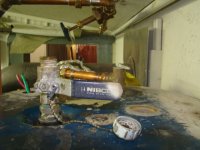
Yesterday I finally got everything wired up and both aqua stats are now operating both pumps. I'm going to have to mess with it for awhile to find the sweet spot for both pumps. I also have to do some tweeking on the stove itself and figure out some draft control system and I may also put some kind of insulated shield around part of the stove to try and keep some of the radiated heat inside where it's needed. I would like to keep some of the heat that it puts out to help heat the back part of the shop where there are no loops but don't need all that it putting out.
OP
mx842
Platinum Member
- Joined
- Feb 26, 2011
- Messages
- 878
- Location
- Richmond Va
- Tractor
- Kubota L3301, PowerKing 2414, John Deere 316, Gravely ZT HD 52
Oh, and I forgot to mention that it seems that the little red disk are finally moving from the top of the glass in the flow meters. The disk are not showing much flow all seem to be showing around .2 gpm but I can see water in the glass tubes now and it's at a level about 1.0 gpm. I can open and close the restrictors on the upper manifold and watch the disk and the water level rise and lower as I open and close them.
I bought a couple new flow meters from pex universe and they are not like the ones that came with the manifolds. I went to replace one of the old ones but they didn't want to screw down into the manifold. They started but seemed really tight so I stopped and put the old one back on. I'm going to check with them tomorrow and find out if I got the right ones.
I bought a couple new flow meters from pex universe and they are not like the ones that came with the manifolds. I went to replace one of the old ones but they didn't want to screw down into the manifold. They started but seemed really tight so I stopped and put the old one back on. I'm going to check with them tomorrow and find out if I got the right ones.
Raspy
Veteran Member
- Joined
- Dec 16, 2006
- Messages
- 1,656
- Location
- Smith Valley, Nevada
- Tractor
- NH TC29DA, F250 Tremor, Jeep Rubicon
mx,
You really don't need the flow meters. They are fun to look at and do give you an initial indication of what's going on, but the real adjusting should be done with temperature on the return lines just before they enter the return manifold. Grip each one with a couple of fingers and thumb. Remember that temp and go to the next one. With all of the adjusters open, find the warmest ones and turn them down a bit until, after some time, they all feel about even.
If you are not feeling much warmth on these lines, you should get a higher head pump.
CalG
Super Member
- Joined
- Sep 29, 2011
- Messages
- 9,193
- Location
- vermont
- Tractor
- Hurlimann 435, Fordson E27n, Bolens HT-23, Kubota B7200, Kubota B2601
Agree with Raspy, but don't be in a hurry to make adjustments. Give the floor an hour or more after the present pump starts running. Then observe inlet temperature before being critical of the return temp.
If there is not enough heat going INTO the floor, All the returns will be cold. ;-)
If there is not enough heat going INTO the floor, All the returns will be cold. ;-)
Raspy
Veteran Member
- Joined
- Dec 16, 2006
- Messages
- 1,656
- Location
- Smith Valley, Nevada
- Tractor
- NH TC29DA, F250 Tremor, Jeep Rubicon
Agree with Raspy, but don't be in a hurry to make adjustments. Give the floor an hour or more after the present pump starts running. Then observe inlet temperature before being critical of the return temp.
If there is not enough heat going INTO the floor, All the returns will be cold. ;-)
Exactly.

Here are some similar links:
- Replies
- 42
- Views
- 7K