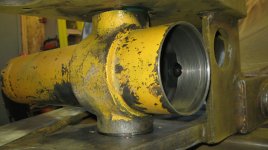
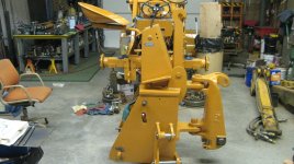
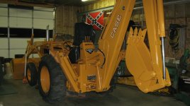
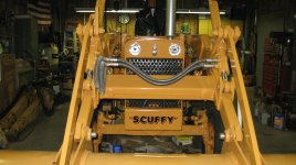
My last picture post, addressed the swing cylinder rebuild and machining parts for the cap pins and trunnion bushings, so to bring you up to date on some of the things I've been doing on that end of the tractor, I've decided to show you what I have been doing to restore the boom and it's parts. Got real busy with a lot of projects and side jobs, so it has set this project back a couple of months, so I know it's been some time since my last post.
I designed and fabricated a set of arms to hold the boom and stick (some call it a dipper) and the bucket when it's stowed or in it's full up position while using the loader or transporting the machine. As most of you will recall; the boom on a 530CK came with a chain on each side that one could hook up and hold the boom in the stowed position. Most of the hoes that I've seen have the chains busted off or discarded. So I tried to come up with a useful solution, you can be the judge as to whether I succeeded or not.
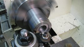
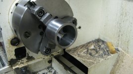
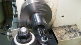
Here is a shot of the start of the oversized washer that is situated on the opposite side of the 2" dia. boom pivot pin. I'm machining a recess so that only the outer face will contact the boom body and it will bear on the most surface giving it more power to hold that pin in place. I'll be parting it off at about 3/8" thick from the face as you can see, and later in the pictures you will be able to see it in place and see it's function.
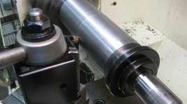
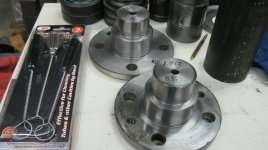
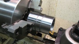
In this shot you can see the start of a series of 2" ID. bushings for both the lower boom pivot pin and the upper dipper pin. It takes 2 per bore and they were a pain to make and fit. Because I don't have access to a line boring machine, I had no way to straighten out those bores and had to machine each bushing's outer diameter different with a few thousands taper to fit the wallowed out bores of the boom. But in the end they all had a good interference fit except for one which I had to scrap and make over again. The procedure that I used to machine the taper was: machine the outer diameter of each bushing using maybe 5 steps (each step a few thousands different from the adjacent step) then connect or blend them using a file as the bushing was turning. Then give the taper a final polishing with some emery cloth. Works great!
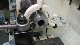
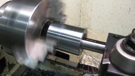
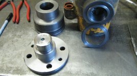
Just making one of the many washers that fit on my pins, between the bosses and snap rings. I would face the material put a nice chamfer on the OD and ID, then part off the washer at the correct width. I never could find real flat and uniform washers that you weren't required to buy a bunch of a particular size, and the price made it prohibitive to do. This was a inexpensive solution, it worked well.
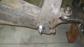
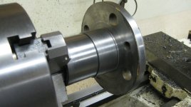
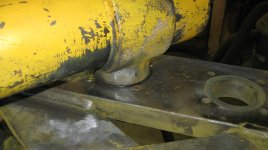
Here is the 2" dia. pivot pin between the tower and boom. If you look closely you can see the washer that I was turning in the first picture. I used 8620 alloy steel for the pin and the washer was machined out of 1020 DOM. (By the way, those of you who build or dabble around with the AR-15 platform have probably noticed that the bold carrier is made out of 8620 alloy steel, pretty strong stuff!) I was able to get the tower mounted with final adjustments to the backhoe frame, and was temporarily attaching the boom to check the fit of both pivot pin and the swing pins below and behind the pivot pin.
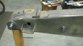
Along the way I made the pivot pin and washers for the connection between dipper and boom. Also made a new pin and washers for the boom cylinder and boom. What is not visible are all of the interior bushing that were mentioned earlier, they are covered by the washers. But the boom and it's parts are now all clean and ready for paint and decals.
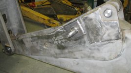
OK, here is a shot of the pins and pads that I welded onto the boom, that the arms for holding the boom up will connect to. I threaded the ends and of those pins and so that I could put nuts and washers on to keep the arms from ever sliding off.
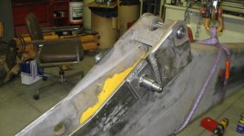
Another angle showing the arm pins and the new pin I machined for the dipper cylinder on top.
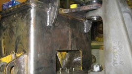
These two brackets at the top of the picture were placed so there was no interference between the tower at full swing side to side and those brackets. I pre-bored the holes for the cross rod before-hand in those brackets, then aligned them before welding them up.
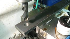
Here is one of the arms, I did a pre-bore with a 1" dia. drill then enlarged the hole with and offset boring bar to a final dia. of 1 1/2". The flat bar is 3/4"x3"- A-36 or what everyone call mild steel.
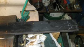
Here is the other end of that arm. I cut the pattern with a cutting torch then welded small stock onto both top and bottom of that end to give additional strength. Then finished up the profile with my mill and a rougher end mill for final shape, which you can see in following pictures.
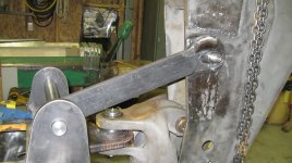
This is what it looks like in the first fit-up. I had to get the correct sizing for length between brackets and pins or the boom cylinder would not lift far enough for the hook to engage the pins. It was sort of trial and error.
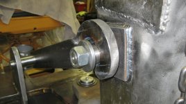
You can see here the nut and washer that I explained earlier how that fit and visually see what they do. After making one up, I then clamped both up together so that my final machining made them identical.
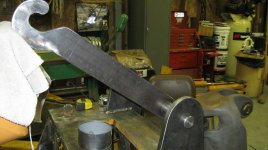
Just more of the fit up process.

The hook end and this picture shows how the 2 pieces steel welded top and bottom thickens and helped form the final shape of the hook.
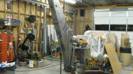
I just included this picture to show the over-all function of the device. The overhead crane was indispensible in the raising and lowering of the boom!
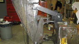
Side view.
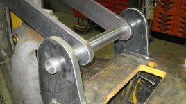
Close-up of the connection and frame brackets.
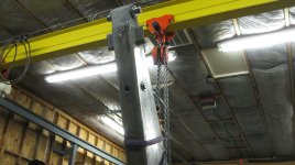
I had to use my hand fall to lift and manipulate the boom. My Coffing electric 2 ton hoist would not lift high enough to bring the boom up the distance that was needed, slower than electric but what a man saver.
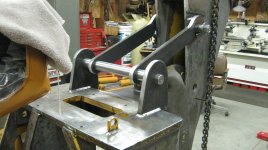
OK, here is a final fit up before tack welding and final weld.
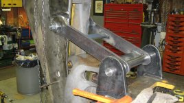
This shows the cross bars and stiffeners in the final welding. All that is remaining is to pull the shaft out cut it to length then groove both ends for the snap rings and get some paint on! :thumbsup:
