- Joined
- Aug 31, 2001
- Messages
- 66,099
- Location
- South Bend, Indiana (near)
- Tractor
- Power Trac PT425 2001 Model Year
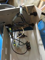
Moss, you have drawn it correctly. The two wires going out to the left are going to the float switch, and so as long as the “silence” switch is set to “alarm” (which it is not in your diagram), the system is armed and ready to go in as soon as the float switch is activated.
The problem, of course, is that one of those internal switches in your diagram does not seem to be working properly. I did check both switches for continuity, and they are as expected. Resistance is infinite when they’re open, and less than one Ohm when they’re closed.
When I had another look at it this weekend, the buzzer would hum like it wanted to go off, but did not always work its way into a full buzzer mode. However, if I activated the test switch, the buzzer would come right on full.
I think I may be dealing with some sort of intermittent electrical short, so I’m going to find a couple more switches and see if they will do the trick.
What I don't get about that circuit is that when the switch is set to alarm, both sides of the buzzer are connected together through the lamp. Nothing can happen as only one end of the circuit is connect to a white wire and the other end of that circuit is connected to an open pole on the test switch.
")