sriddle1
Silver Member
- Joined
- Apr 2, 2014
- Messages
- 234
- Location
- SW New Hampshire
- Tractor
- ACTIVE: JDX730 DAYS GONE BY: JD3010, JD790, JD425
Good Morning,
A cool crisp morning in SW New Hampshire BUT PLEASE SEND RAIN........
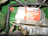
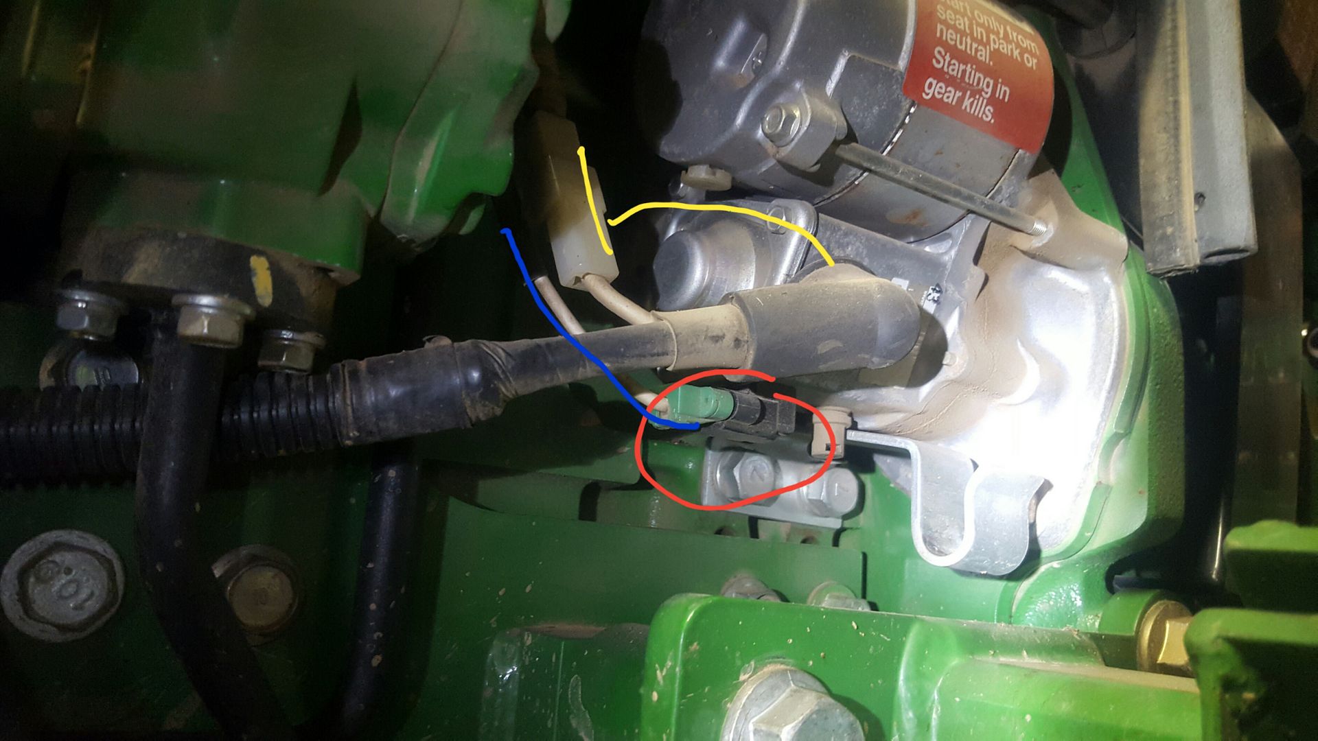
I'm trying to test out the voltage readings coming to the Stop Fuel Solenoid. I'VE attached the appropriate Wiring Diagram for my '05 JD 790 Production/Serial Number. Wondering if someone could walk me thru the Multi-Meter Red/Black Probe placements and readings I should get. I can see by my "un-trained" eye the White-Red-Black wire connector coming from the Solenoid connects to a Harness Connector - Solenoid White Wire connects to Harness White/Blue wire to "Time Delay Control Module" PN: M803344 + "K2" Fuel Relay. The RED coming off the Solenoid connects to Harness Green/White to "K2" Fuel Relay. If I disconnect the Solenoid Connector, place the Tractor in the Start Position, what readings should I get from the Harness side connector points. Please spoon feed me where I need to place the probes while taking measurements. If the readings at the Harness are good I would "Assume" (you know that they say about that) the Fuel Solenoid is Bad. If the readings aren't good then again I can assume the "Time Delay Control Module" PN: M803344 upstream is bad.......
A cool crisp morning in SW New Hampshire BUT PLEASE SEND RAIN........
I'm trying to test out the voltage readings coming to the Stop Fuel Solenoid. I'VE attached the appropriate Wiring Diagram for my '05 JD 790 Production/Serial Number. Wondering if someone could walk me thru the Multi-Meter Red/Black Probe placements and readings I should get. I can see by my "un-trained" eye the White-Red-Black wire connector coming from the Solenoid connects to a Harness Connector - Solenoid White Wire connects to Harness White/Blue wire to "Time Delay Control Module" PN: M803344 + "K2" Fuel Relay. The RED coming off the Solenoid connects to Harness Green/White to "K2" Fuel Relay. If I disconnect the Solenoid Connector, place the Tractor in the Start Position, what readings should I get from the Harness side connector points. Please spoon feed me where I need to place the probes while taking measurements. If the readings at the Harness are good I would "Assume" (you know that they say about that) the Fuel Solenoid is Bad. If the readings aren't good then again I can assume the "Time Delay Control Module" PN: M803344 upstream is bad.......
Attachments
Last edited: