3-Point Hitch 3 point hitch won't lift

   / 3 point hitch won't lift
  • Thread Starter
#61  
Here's where I am.

The big picture...

P1040701.JPG

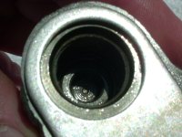
The clyinder the valve is rusted in. Note that the valve is somewhat hollowed out to allow for spring placement. The valve is in the lower left portion of the pic and the hollowed out part is in the middle with the dimple in the center.

P1040698.JPG

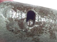
My access (besides from the open end of the clyinder). Here you can see the valve on bottom side of the access hole (sorry, a bit out of focus).

P1040700.JPG
 
   / 3 point hitch won't lift #62  
Here's where I am.

The big picture...

View attachment 108621

The clyinder the valve is rusted in. Note that the valve is somewhat hollowed out to allow for spring placement. The valve is in the lower left portion of the pic and the hollowed out part is in the middle with the dimple in the center.

View attachment 108619

My access (besides from the open end of the clyinder). Here you can see the valve on bottom side of the access hole (sorry, a bit out of focus).

View attachment 108620


A bit of Macro and you'll get it perfect every time. Now, I look at the last picture, granted the hole was rusty but hardly believe that rust can be developed all the way thru in a geometric shape. In your original pics you mentioned that rust goes all the way thru valve body. I think what you see there is some sort of bleed port. If you look at tie rod and their range of motion, and with the feed back arm that is attached to the spool valve. when the 3.pt arrives at designated height then the spool valve will go to "neutral" position. Neutral position is where all the fluid is bypassed to the sump. Once you have reached the intended 3 point height, at that point no more hydraulic flow is needed and since the hydraulic is "live... running all the time" all the fluid has to be diverted to the sump to provide fluid make up for the pump operation. I believe, that might be some sort of release/drain passage way and the hole is not caused by rusting. I spry thru the hole to hopefully loosen up #7 (Hyd valve). How did #12 and # looked like?

JC,
 
   / 3 point hitch won't lift
  • Thread Starter
#63  
Probably as you described but check out the explaination (all greek to me) on pg 102 of FO-44 under Paragraph 186.

Here's what I now know about the clyinders.

  • There are actually 4, 3 with front access and 1 with rear access.
  • When installed the top clyinder with the hole is NOT closed off fron the 2nd cylinder (front access with the hex bolt).
  • I was using a dental tool to loosen rust and found that where the hole is there is also a connection to the 2nd clyinder. Also, when I sprayed fluids in the 2nd clyinder access hole (on the side and the way you access the cylinders by only rremoving the outer valve plate w/3 bolts) the fluids came out the hole on top when turned upside down.
  • Through the access holes in the 2nd and 4th clyinders I found no rust and the metal was all nice and shiny so I didn't take those apart. Besides, to remove those parts in 2nd and 4th clyinders I'd have to jack with the double nuts.
I'm thinnking that you're correct that it shouldn't be so rusted that it disallows the valve in question to come out.

What do you think about this scenario...

What if the valve in question is actually pressed or hammered in. However, if this is the case then how would one remove it without tapping the center and using a puller to get it out? The book says nothing about that, just only to remove it during an overhaul.

Also, is it possible that the 1/8 inch play I got is all there is supposed to be? If this is the case then the spring holds the valve closed and the pressure pushes the valve open (the 1/8") thus allowing flow.

I know the above scenario is wishful thinking but I've begun to put it back together and see what happens with the lift. At least I'll know what I'm getting into if it doesn't work and can investigate the removal process before tearing her apart again.

It doesn't take much to take it apart and the only waste is a bit of silicon gasket material.

You thoughts?
 
   / 3 point hitch won't lift
  • Thread Starter
#64  
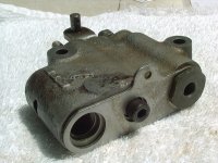
OH... the hole on top (rusted) was not caused by rust. This hole is factory but isn't shown in the diagram. You mentioned accessing the spool valve by removing the 3 bolts and lubing through the access points When you take off the cover how many holes can you lube? 2 I bet.

Those 2 are the 2nd and 4th clyinders. There is no maintenence access to the 3rd cylinder other than taking the rear banjo bolt out.

The top clyinder access is the hole in the top.

What I summized happened is that the valve cover plate gasket failed and over the years water accumulated on top to the valve assembly. As the rust spread it made it's way to the hole on top. Now, there may be some rust residue in the 2nd cylinder but I didn't see any through the access hole(s).

The mechanics move fine other than the valve in question (top clyinder)
 
   / 3 point hitch won't lift #65  
Probably as you described but check out the explaination (all greek to me) on pg 102 of FO-44 under Paragraph 186.


You thoughts?

Sevan,

Please look at the pic below. It is difficult to cover the operation with one paragraph. If you look at the porting and get
yourself some colored pencil can determine the flow routing. It shows hyd fuel being pumped from the sump, how it travels
to main safety relief valve and at then in the hyd spool valve. There are many things happening for the fluid to travel thru
different openings and ports. You can read it very carefully and figure out and most likely you'll forget it the next day... I did:eek:
bottom line is the concept;

1) hyd system is live and always pumping when the tracrtor is on.
2) Takes finite amount of liq to fill the cylinder for any given height.
3) when the height is archived something has to be done(I.e, as you can not suck out of the bottle conversely can not put
more in it than the volume allows).

4) when the 3 pt height is archived all the oil has to be diverted to sump.
5) if you were to lower the 3 point then some oil has to go back thru the same spool. You got a busy cross section with traffic
cops and street light to regulate the traffic and in this case oilflow.

The reason I suggested to do this at the last option was the complexity of inside and adjustment that comes with it. Any how,
even I would do exactly the same as you are doing even if it was futile, if nothing else it is a great learning opportunity. I'd put
the stuff back and give it a go, may be you have cleared the obstruction... I hope.

By the way, I kind of asked this question several times, I know the FEL works, but look at the flow arrow and where it ties to the
bottom of the spool valve( that is the banjo connection on the inlet to the spool). Have you actually loosened it and observed
flow prior to valve spool assembly??


JC,

p100101ni0.jpg
 
   / 3 point hitch won't lift
  • Thread Starter
#66  
No... I've not loosened any banjo connections then ran the tractor. Is that next?

I'm no newbie to drawings but the ones I know are building architectural drawings and not schematics. The one you posted is backwards and upside down from the actual positioning of the control valve assemble.

Take a look at this one.

p100101ni0 new.JPG

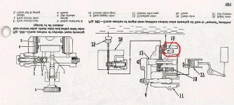
Note that I repositioned the figure to where the unloading valve (circled in red) is on top and I kept calling it the top clyinder and the rusted hole is on top. This is how the configuration is in reality. Forgive me for not reading schematics as well as arch drawings. What is confusing to me is how the sump ends up on top! I can imangine flow moving upward through the assembly but not once it leaves the assembly through the HOLE ON TOP then defying gravity... ends up in the sump on top.
 
   / 3 point hitch won't lift #67  
No... I've not loosened any banjo connections then ran the tractor. Is that next?

I'm no newbie to drawings but the ones I know are building architectural drawings and not schematics. The one you posted is backwards and upside down from the actual positioning of the control valve assemble.

Take a look at this one.

View attachment 108623

Note that I repositioned the figure to where the unloading valve (circled in red) is on top and I kept calling it the top clyinder and the rusted hole is on top. This is how the configuration is in reality. Forgive me for not reading schematics as well as arch drawings. What is confusing to me is how the sump ends up on top! I can imangine flow moving upward through the assembly but not once it leaves the assembly through the HOLE ON TOP then defying gravity... ends up in the sump on top.


Sevan,

I know your are mistaken. The pdf is posted is accurate and in the right orientation. You are looking at the spool valve from the inside. What is shown on the FO-44 is looking from the outside and from right side of th tractor. The numbering I'm going to use here now is from FO-44 diagram and not from NH site. # 4 drop poppet valve and #12 control valve spool is shown on the left side of the assembly and you picture looking at it from the inside shows the two on the right side... That's all there is to it. It may be confusing to you but in pdf the sump is below the valve like it should be. Any diverted/unused oil flow from the spool valve assembly is ejected by pressure from the valve but by gravity is returned to the sump just the way the pic shows it. By the way , although the configuration is correct it is only diagrammatic to show things happening and direction of flow. #4 and #12 go in and out by the action of lift control handle. It is not difficult to see as when #4 travels to the left causes the fluid to squirt out hence bringing the lift arm down. #12 moving to the left causes the fluid to be diverted back to the sump blocking flow to #19 check valve. I have to admit the hole on top of the assembly is not shown on the drawing, but again pic shown on FO-44 is diametrically correct to understand the flow scheme.


No... I've not loosened any banjo connections then ran the tractor. Is that next?

The answer is "it should have been done prior to spool valve disassembly". I have said it on several posts prior to the spool disassembly that we have to verify the flow to inlet of the spool before trying to check the spool's innards. I have also said checking the spool should be the absolutely the last option. You may need to read my posts a bit more carefully. You also need to look at FIG.288 for adjustment of #12 and #4 as it is important in proper operation of the lift system.

JC,
 
   / 3 point hitch won't lift
  • Thread Starter
#68  
No real need for me to understand the diagram... the only important thing is that I have all the parts in the diagram and how it's orientated makes no difference to me. Thanks for the explaination of how the thing works.

What I do know is the unloading valve in my control valve is NOT closest to the sump.

I haven't missed your instructions from the beginning to check flow and I thought that's what we were doing when we checked the relief valve. It was only between the time of your trip and my call to the NH dealer that I got sidetracked. If I hadn't been misled by the dealer and told to take out the 7 bolts and soak the whole unit, I would never have gone there (he made it sound like a piece of cake - there we go with the food references again). I never intended to take apart the control valve but once it was out I figured, what the ****!

However, I did not take the control valve completly apart. I took your advice of removing one bolt at a time. I chose the bolt (cylinder) closest to the rust which only has 3 parts in it, an o-ring, a spring, and the unloading valve. Since I had no luck getting the unloading valve out but did get it to move a bit I saw no need to move on to the other clyinders. Again, I don't mind taking the thing out again AFTER we determine that's the actual cause.

I assume you've been systematically working your way to bigger and better things (exactly the way my engineers do things) and again, I would never have taken a side road had I known what really needed to be done to 'soak' the parts.

So... yesterday I put it back together with silicone gasket and let it set up. This morning I have lift.

It's not the way it was in that the lever adjustment is off. That is... where it used to be at full lift is where it now starts to lift. I was very careful NOT to mess with the adjusting nuts on the control valve.

What do you think ought to be next?

Thanks for continuing to help even after I got sidetracked!
 
   / 3 point hitch won't lift #69  
No real need for me to understand the diagram... the only important thing is that I have all the parts in the diagram and how it's orientated makes no difference to me. Thanks for the explaination of how the thing works.

What I do know is the unloading valve in my control valve is NOT closest to the sump.

So... yesterday I put it back together with silicone gasket and let it set up. This morning I have lift.

It's not the way it was in that the lever adjustment is off. That is... where it used to be at full lift is where it now starts to lift. I was very careful NOT to mess with the adjusting nuts on the control valve.

What do you think ought to be next?

Thanks for continuing to help even after I got sidetracked!

Unloading valve #15 is a check valve, removing the nut in front of it, putting a shop rag in front of the hole of and putting some compressed air in the spool inlet may move the check valve out for inspection. It pretty much how you push the piston out of break caliper with compressed air. That might do the trick. Sump is just the bottom of differential, oil can be sprayed any which direction from the spool but ends up in the bottom. when I opened my hyd cyl, the inside housing had lots of oil droplets on everything and they all eventually drip and end up in the bottom of diffy housing.


So... yesterday I put it back together with silicone gasket and let it set up. This morning I have lift.


so is the lift problem solved?.... Right?


I think the lever adjustment is off. Look at the diagram below, Nut "N" should be adjusted correctly. did you mess with the nut, or did you take it off at the clevis pin?

If you did at the clevis pin nut no adjustment is needed on the exterior lift arm feed back. this feed back arm tells the spool valve "I'm good" , no more oil or basically normal position of the spool valve at a given arm height.

p9697jo5.jpg

dsc03645xo0.jpg


The spool inside need to be adjusted if it is not acting right. In my previous post I had reference to paragraph and Fig # 288 where it gives explanation on how to do it. need to set a gap per spec.

p102103ci2.jpg


I hope this helps,
JC,
 
Last edited:
   / 3 point hitch won't lift
  • Thread Starter
#70  
I won't be completly sure it's 'fixed' until I get out there today and use it. All I've done so far is to start the tractor and check the lift.

I removed the clevis pin and didn't mess with the nut.

Also, I spoke with my brother who used it to cut grass and said he set the round positioning knob (on the right of the lever in your diagram) to the mower deck height so I may be mistaken about where the lift actually shuold be.

I'll post again after I use it and can get a better feel for what's going on.

Also, just because it lifted 2 or 3 times as a test doesn't mean it's not going to start acting up once used a bit.

I'd almost bet the farm that the adjusting nuts on the valve were not moved during my investigation.

Thanks,
 

Tractor & Equipment Auctions

2017 MITSUBISHI OUTLANDER SPORT (A52472)
2017 MITSUBISHI...
HAY KING RENOVATOR (A52472)
HAY KING RENOVATOR...
2012 CHEVROLET 2500 HD SERVICE TRUCK (A51406)
2012 CHEVROLET...
CHANDLER 20FT 16 TON HYDRAULIC SPREADER (A52472)
CHANDLER 20FT 16...
HAMM 3205 SMOOTH DRUM ROLLER (A51242)
HAMM 3205 SMOOTH...
KUBOTA RTV X1100C UTV (A51406)
KUBOTA RTV X1100C...
 
Top