360* Rotating Back Blade Project

   / 360* Rotating Back Blade Project
  • Thread Starter
#111  
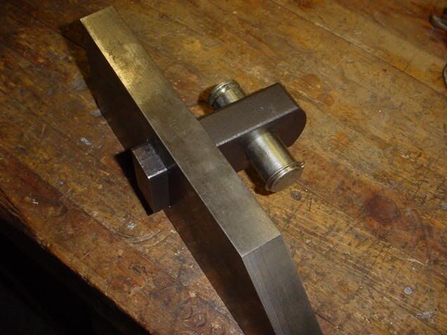
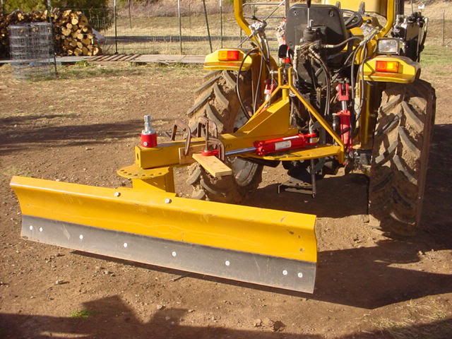
This is a closer look of the mount from the other side:


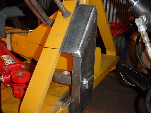
And an overall shot of how far the swing is capable of moving:


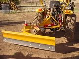
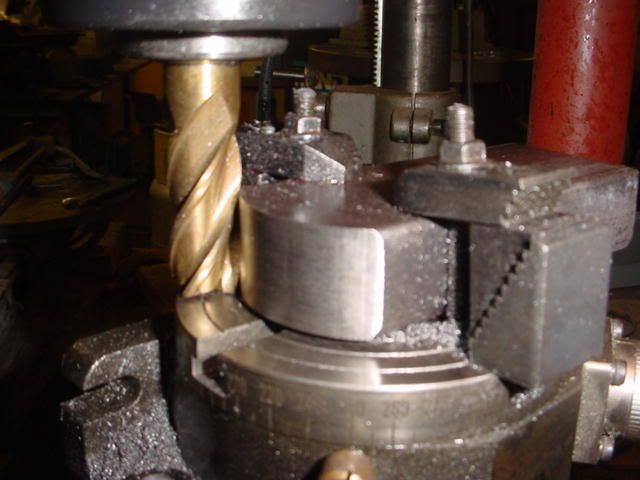
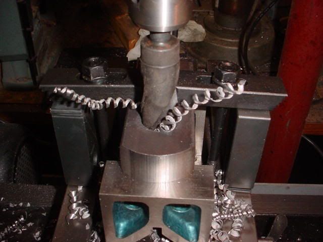
Next is to complete the cylinder mounts (for both ends of the cylinder).
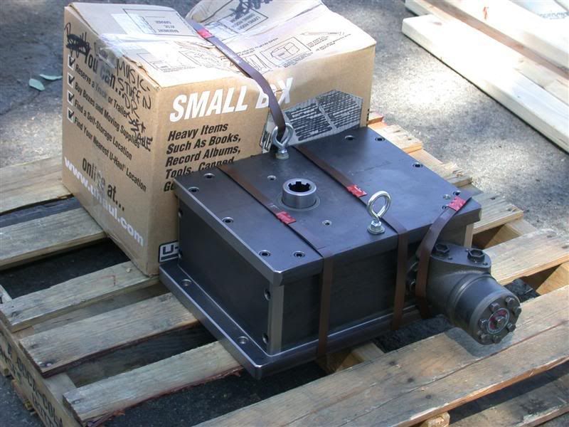
Make a mount for the Gear Box that Rob has completed and add a hydraulic valve to control the swing offset cylinder.


Larry
 
   / 360* Rotating Back Blade Project #112  
Larry,

Where are you going to mount the valve to control the swing and rotation. The back of your tractor already looks like a plumbers nightmare.:eek: 
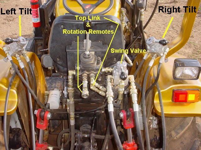
What with the two tilt cylinders and valves the toplink cylinder and valve--is that the center "joystick" control? will the joystick control the rotation too?

Mike
 
   / 360* Rotating Back Blade Project #113  
Larry, not sure that it will be good with position how did you set it up ???
Cylinder is too parallel with blade frame, and you will have big axial forces, when cross force will be low.
Put fixed bracket as far as possible right (look from rear side) to increase angle between frame and cylinder (visible when frame is straight) and put one cylinder on each side.
Maybe cylinder will survive, but mounting bracket will bend first time when you hit some stump.

I can't see from a pic how big is blade and tractor, so how strong everything will be.

Next suspition: that shear pin on rotating axle seems the weakest point on your construction. Look at ratio between force on one end of blade and on shear pin.
Locking pin, used before your modification, was on significally bigger radius, maybe 8" towards 1" now, and was about 1"dia, and your shear pin is maybe 1/2"

I'm supporting you on that project, and take my complaints in good faith.
 
   / 360* Rotating Back Blade Project #114  
ZJ_HR said:
Cylinder is too parallel with blade frame, and you will have big axial forces, when cross force will be low.


i agree, if you look at my landpride (aka ford) blade which is built for a hydrolic offset, nutral postion has the cylinder offset about 20deg. you can see the holes were the cylinder would be (it was removed in the pic as i was preping for paint)


   / 360* Rotating Back Blade Project #115  
Mornin Rob,
As Larry just stated previously, very nicely done and an excellent job on the documentation !!!

Just a quick question, Im guessing that you have a very minimal amount of backlash between the worm and worm wheel so the backblade has next to no play ? Am I on target here ?

Thanks again for all the great pics and videos ! :)
 
   / 360* Rotating Back Blade Project
  • Thread Starter
#116  
MJPeterson - ....looks like a plumbers nightmare......will the joystick control the rotation too?

I guess it could be considered a plumber’s nightmare if it was all corroded, leaking and could not be access for repair. All the valves are conveniently located for easy access while in the seat, or standing behind hooking things up. I think all those valves, hoses, and raw hydraulic power at my fingertips are cool. It’s really not all that bad is it?

You are correct about that FEL joystick valve on the back of the seat, one spool will control Blade Rotation, the other spool for the Top Link. The valve for swing is installed in series with the FEL valve:


ZJ HR - ....Cylinder is too parallel with blade frame, and you will have big axial forces, when cross force will be low.....Locking pin, used before your modification, was on significally bigger radius, maybe 8" towards 1" now, and was about 1"dia, and your shear pin is maybe 1/2"

I agree about the parallel cylinder - The cylinder is placed such that there is close to 90* of swing – similar to a FEL grapple cylinder. When the cylinder is located further away from the swivel point, the range of swing motion is significantly reduced. To prevent failure, there will be a mechanical stop at each end of swing travel along the radius. This will hold the swing in place at the end of cylinder travel, reducing stress on the cylinder mount. I will show pictures once those stops are installed. The 1/2” shear bolt is to protect the teeth of the gears. This is a one of a kind experimental prototype, so I’m sure there will be some adjustments needed after I evaluate it’s performance.

Schmism –
That’s one beefy looking blade mount you got there. What is the range of swing you get with it? What is the retracted / extended distance between the clevis holes on your cylinder? Why are there two holes in the cylinder mount? Do you have to manually move the cylinder to different holes to get full range?

I thank everyone for all valuable feedback.
Larry
 
   / 360* Rotating Back Blade Project #117  
scott_vt said:
Mornin Rob,
As Larry just stated previously, very nicely done and an excellent job on the documentation !!!

Just a quick question, Im guessing that you have a very minimal amount of backlash between the worm and worm wheel so the backblade has next to no play ? Am I on target here ?

Thanks again for all the great pics and videos ! :)
Scott,
Yes, you are right on target. Most gears I've done have been place center to center using pitch diameters plus .004" to avoid binding. In this case, I placed them right on pitch diameter to avoid backlash.
 
   / 360* Rotating Back Blade Project #118  
I finally got Larry's gearbox strapped to a pallet and FedEx came by a few minutes ago to pick it up. So it's on it's way to New Mexico today.


I added a couple eye bolts so Larry can lift it into position. Then he can take them out and replace them with the 3/8-16 SHCS that go in there. I also wrapped up the gear box and the "care package" with plastic after that picture was taken for it's journey home.
 
   / 360* Rotating Back Blade Project
  • Thread Starter
#119  
Hi Rob,

Thanks for the great news that the Gear Box is on it's way. You strapped it down good, so it will arrive safely.
Great picture of the completely assembled product. It will look even better when installed.

I'm pretty close to getting the swing cylinder installation finished. Today I completed the swing cylinder mount bracket, all that's left is to weld the bracket in place, make the mounts for the gear box - which fortunately are pretty simple.

Here is what I did today -
Used the rotary table to round the end of the cylinder mount:


Drilled a 1" hole for the cylinder clevis pin.
I think the drill is sharp based on the even shavings , and the fact it went through like butter.


Then I milled out a 1" x 2" slot right though the 1" thick bracket so that the clevis mount could never bend or break off:


All ready to weld:


Got dark on me :confused: So all I could do is get it ready to weld into place:


Larry
 
   / 360* Rotating Back Blade Project #120  
Mornin Larry,
Nice work ! BTW, did you notice how Rob included an eye hook on that gear case ? ;) :)
 

Tractor & Equipment Auctions

2014 Dynapac CC4200 Tandem Vibratory Roller (A51039)
2014 Dynapac...
71065 (A49346)
71065 (A49346)
2018 FORD F-150 (A50854)
2018 FORD F-150...
4- 6 DRILL COLLARS (A50854)
4- 6 DRILL COLLARS...
2020 John Deere 6110M 110HP 4WD Agricultural Tractor (A49461)
2020 John Deere...
Komatsu D39PX-24 Crawler Tractor Dozer (A49346)
Komatsu D39PX-24...
 
Top