You are using an out of date browser. It may not display this or other websites correctly.
You should upgrade or use an alternative browser.
You should upgrade or use an alternative browser.
360* Rotating Back Blade Project
- Thread starter GuglioLS
- Start date
- Views: 61759
More options
Who Replied?
/ 360* Rotating Back Blade Project
#121
OP
GuglioLS
Veteran Member
- Joined
- Feb 13, 2005
- Messages
- 1,155
- Location
- Edgewood, NM USA
- Tractor
- Jinma 354, 1953 Ford NAA Golden Jubilee, Komatsu Bulldozer
Here's the progress report for work I completed this weekend -
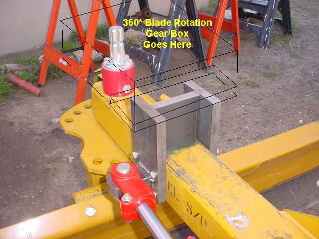
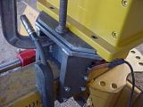
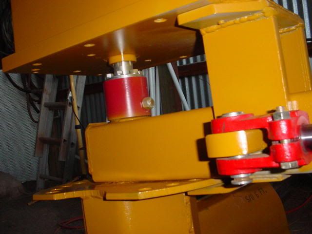
The swing offset cylinder mount is done. It's an integral part of the Gear Box mount system. The steel used for the mount is 3/4" x 4" wide hot rolled flat bar. It's attached to the blade boom with four 3/8"-16 SHCS (socket head cap screws). The gear box Rob Machined and fabricated for me, should arrive sometime Monday 4/2/07
This picture shows the cylinder mount and an outline of where the gear box will rest on top and be attached to it.

This 23 second video (2.1 meg) shows the swing cylinder in action:
This is a much larger 59 seconds (5.3 meg) video. showing the Swivel, and Top & Tilt.
The plan is to get the gear box mounted, hydraulics connected, then performance tested this coming weekend. I can hardly wait.
Larry
The swing offset cylinder mount is done. It's an integral part of the Gear Box mount system. The steel used for the mount is 3/4" x 4" wide hot rolled flat bar. It's attached to the blade boom with four 3/8"-16 SHCS (socket head cap screws). The gear box Rob Machined and fabricated for me, should arrive sometime Monday 4/2/07
This picture shows the cylinder mount and an outline of where the gear box will rest on top and be attached to it.
This 23 second video (2.1 meg) shows the swing cylinder in action:
This is a much larger 59 seconds (5.3 meg) video. showing the Swivel, and Top & Tilt.
The plan is to get the gear box mounted, hydraulics connected, then performance tested this coming weekend. I can hardly wait.
Larry
MJPetersen
Veteran Member
GuglioLS said:I can hardly wait.
And vicariously a whole bunch of us who have been following your thread.
Mike
Corm
Gold Member
- Joined
- Apr 6, 2000
- Messages
- 352
- Location
- Fairfax, Franklin County, Vermont
- Tractor
- 1999 Cub Cadet 7260, 1953 Farmall Super A
Gentlemen, outstanding work! Thank you for taking the time to document and post this information. Fascinating to watch an idea grow like this!
Corm
Corm
OP
GuglioLS
Veteran Member
- Joined
- Feb 13, 2005
- Messages
- 1,155
- Location
- Edgewood, NM USA
- Tractor
- Jinma 354, 1953 Ford NAA Golden Jubilee, Komatsu Bulldozer
All the Gang following this thread, thank you for all your positive comments, compliments and encouragement on this project.
I now have the gear box in my possession!!!
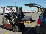
I called FedEx early this morning - they said the driver left without it because they had no idea where I live and that they could deliver it MAYBE Wednesday or Friday - I said the heck with that - I'm gonna take matters into my own hands and pick it up myself. - So I did.
Here's the forklift pulling up to my company van -
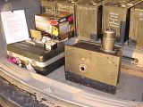
I removed the shrink wrap Rob put on there - man he used lot's of that stuff - it was tough to get off. Then I cut the banding and muscled the gear box off the pallet into the back of my van. Rob was not joking, that bugger is H-E-A-V-Y.
Here is a shot of the gear box ready for it's trip home. My van was doing wheelies all the way
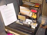
In addition to the gear box, Rob sent me a care package containing three precision dial indicators so that I don't have to machine blindly anymore. When Rob comes to visit me this summer he can show me how to use them properly. Additionally he sent me a nice set of those corn cob roughing mill bits that I was drooling over the first time I saw him use them. AND a 3 MEGA candle power flashlight so I can burn holes though the night sky. AND all the blue prints of every detail of the Gear Box he precision machined for me. AND, AND a really nice personal heart felt letter, thanking me for allowing him to be a part of this HUGE project. That was the icing on the cake for me - what a great guy Rob is, I am so grateful to him.
This are a shot of all the extras Rob sent me:
On the way home I stopped at NAPA and picked up two gallons of 85-90 gear oil. As thick as that stuff is, It might take me all week to fill it up. I have work in my "real" job all this week to catch up on, so getting it installed properly will most likely take place this weekend.
OOPS - I almost forgot, I have to travel to San Jose, CA for a couple of days early this coming Easter Sunday Then a few weeks after that My Wife and I travel to Cabo Mexico for a company "meeting" and a needed get away. Maybe I should play hooky & call in sick? - we'll see, it's gonna be hard for me to keep my mind on anything else, knowing I am so close to getting the gear box installed and working. On the other hand, I don't want to rush this as I need to make sure this project and thread come to the proper conclusion.
Thanks for your indulgence,
Larry
I now have the gear box in my possession!!!
I called FedEx early this morning - they said the driver left without it because they had no idea where I live
and that they could deliver it MAYBE Wednesday or Friday - I said the heck with that - I'm gonna take matters into my own hands and pick it up myself. - So I did.Here's the forklift pulling up to my company van -

I removed the shrink wrap Rob put on there - man he used lot's of that stuff - it was tough to get off. Then I cut the banding and muscled
the gear box off the pallet into the back of my van. Rob was not joking, that bugger is H-E-A-V-Y.Here is a shot of the gear box ready for it's trip home. My van was doing wheelies all the way

In addition to the gear box, Rob sent me a care package containing three precision dial indicators so that I don't have to machine blindly anymore. When Rob comes to visit me this summer he can show me how to use them properly. Additionally he sent me a nice set of those corn cob roughing mill bits that I was drooling over the first time I saw him use them. AND a 3 MEGA candle power flashlight so I can burn holes though the night sky. AND all the blue prints of every detail of the Gear Box he precision machined for me. AND, AND a really nice personal heart felt letter, thanking me for allowing him to be a part of this HUGE project. That was the icing on the cake for me - what a great guy Rob is, I am so grateful to him.
This are a shot of all the extras Rob sent me:

On the way home I stopped at NAPA and picked up two gallons of 85-90 gear oil. As thick as that stuff is, It might take me all week to fill it up. I have work in my "real" job all this week to catch up on, so getting it installed properly will most likely take place this weekend.
OOPS - I almost forgot, I have to travel to San Jose, CA for a couple of days early this coming Easter Sunday
Then a few weeks after that My Wife and I travel to Cabo Mexico for a company "meeting" and a needed get away. Maybe I should play hooky & call in sick? - we'll see, it's gonna be hard for me to keep my mind on anything else, knowing I am so close to getting the gear box installed and working. On the other hand, I don't want to rush this as I need to make sure this project and thread come to the proper conclusion. Thanks for your indulgence,
Larry
scott_vt
Super Member
- Joined
- Oct 5, 2004
- Messages
- 8,089
- Location
- east wells,vt
- Tractor
- 1986 MF 1040, 1942 Farmall A, 1949 Farmall Super A
Mornin Larry,
The best I can tell by the picture, is that you made out like a bandit !
Looking foward to the conclusion !
The best I can tell by the picture, is that you made out like a bandit !
Looking foward to the conclusion !
thunderworks
Silver Member
You guys have unbelievable skills. I wished you loved near me and were both my friend!
I must be missing something though . . . I looked at the movie of the blade and it looked to me as though the blade swung through a wide arc, both directions (I guess with hydraulic cylinders since the gearbox wasn't installed yet). What additional functionality will the gearbox provide that the current range of motion can't handle?
I must be missing something though . . . I looked at the movie of the blade and it looked to me as though the blade swung through a wide arc, both directions (I guess with hydraulic cylinders since the gearbox wasn't installed yet). What additional functionality will the gearbox provide that the current range of motion can't handle?
OP
GuglioLS
Veteran Member
- Joined
- Feb 13, 2005
- Messages
- 1,155
- Location
- Edgewood, NM USA
- Tractor
- Jinma 354, 1953 Ford NAA Golden Jubilee, Komatsu Bulldozer
WELL here is the latest good news -
I had NAPA make me up some paint to match the Leinbach yellow. Turns out Komatsu dozer equipment yellow is a very good match. Also looks very close to Cat yellow
I got the Gear Box suspended in the air on my chain hoist and painted it. Then centered the Blade PTO coupler shaft under the gear box then proceeded to lower it into place with the chain fall:

When I got close to the shaft all I had to do was rotate the blade by hand a little to get the splines lined up, then lower the gear box a little at a time:
Larry
I had NAPA make me up some paint to match the Leinbach yellow. Turns out Komatsu dozer equipment yellow is a very good match. Also looks very close to Cat yellow
I got the Gear Box suspended in the air on my chain hoist and painted it. Then centered the Blade PTO coupler shaft under the gear box then proceeded to lower it into place with the chain fall:
When I got close to the shaft all I had to do was rotate the blade by hand a little to get the splines lined up, then lower the gear box a little at a time:

Larry
OP
GuglioLS
Veteran Member
- Joined
- Feb 13, 2005
- Messages
- 1,155
- Location
- Edgewood, NM USA
- Tractor
- Jinma 354, 1953 Ford NAA Golden Jubilee, Komatsu Bulldozer
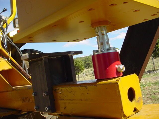
I continued to lower the gear box so that the PTO coupler was engaged and not binding :

Guess what ? All the holes lined up How could this be? This is going much too smoothly I bolted the Gear Box to the bracket I made with two 3/8" SHCS that Rob provided to me in the care package. I doubt those two little screws will hold all the rotational torque. SO Now it's time to add a plate on top of my bracket and push it up against the bottom plate of the gear box to prevent those two little 3/8 screws from shearing off:
Larry
Guess what ? All the holes lined up
How could this be? This is going much too smoothly I bolted the Gear Box to the bracket I made with two 3/8" SHCS that Rob provided to me in the care package. I doubt those two little screws will hold all the rotational torque. SO Now it's time to add a plate on top of my bracket and push it up against the bottom plate of the gear box to prevent those two little 3/8 screws from shearing off:
Larry
OP
GuglioLS
Veteran Member
- Joined
- Feb 13, 2005
- Messages
- 1,155
- Location
- Edgewood, NM USA
- Tractor
- Jinma 354, 1953 Ford NAA Golden Jubilee, Komatsu Bulldozer
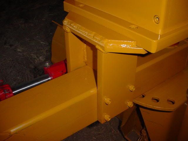
After welding and cooled off, I painted all the brackets:
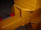
Here's another bottom view showing the coupler completely engaged:

Larry
Here's another bottom view showing the coupler completely engaged:
Larry
OP
GuglioLS
Veteran Member
- Joined
- Feb 13, 2005
- Messages
- 1,155
- Location
- Edgewood, NM USA
- Tractor
- Jinma 354, 1953 Ford NAA Golden Jubilee, Komatsu Bulldozer
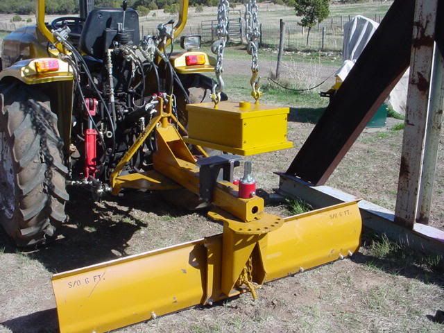
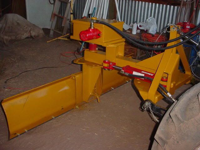
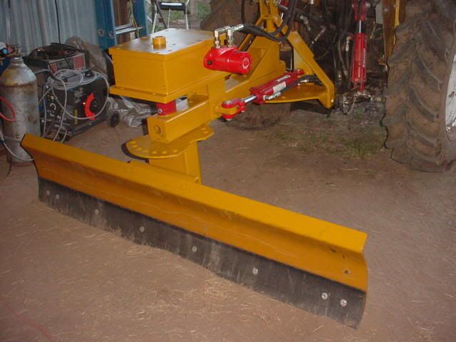
All the painting is now complete. Then I installed the Motor & hydraulic lines with quick connects to my Joy Stick valve I have on the back of the tractor.
Side view:
Back View:

Tractor Seat View:
Larry
Side view:
Back View:
Tractor Seat View:

Larry
OP
GuglioLS
Veteran Member
- Joined
- Feb 13, 2005
- Messages
- 1,155
- Location
- Edgewood, NM USA
- Tractor
- Jinma 354, 1953 Ford NAA Golden Jubilee, Komatsu Bulldozer
OK, HERE IT IS THE MOMENT OF TRUTH:
This is a 33 second Video and is 3 meg:
I think it works !
Larry
OP
GuglioLS
Veteran Member
- Joined
- Feb 13, 2005
- Messages
- 1,155
- Location
- Edgewood, NM USA
- Tractor
- Jinma 354, 1953 Ford NAA Golden Jubilee, Komatsu Bulldozer
This video is from the tractor seat, near the end of the video, I swing the swivel offset to the left:
Because I have installed hydraulic priority flow dividers, I can set the flow rate of the hydraulics. So that the speed of rotation and swing offset is just right (not to fast & not too slow).
I am able to control speed of swing & rotation to whatever I need for the task at hand. All without leaving the seat!
One more major bracket needs to be added to the rear of the Gear Box to completely support it. I will do some REAL dirt moving to check it's real life performance AFTER that bracket is fabricated and installed in place.
Due to my schedule, 100% performance evaluation and testing will be completed in the next couple of weeks.
I hope so far that all of you have enjoyed this little project as much as Rob and I have.
Thank you for your indulgence!
ANY and ALL feedback is encouraged and welcomed.
Larry
tlbuser
Veteran Member
Woo Hoo. The big plan finally comes into action! Looks fantastic from here. Thanks for taking all the extra effort to share with us.
Now that you and Rob will have some free time........I'm thinking about a plc controlled, hydraulically activated, uhf remoted, gumball pickerupper.
Now that you and Rob will have some free time........I'm thinking about a plc controlled, hydraulically activated, uhf remoted, gumball pickerupper.
scott_vt
Super Member
- Joined
- Oct 5, 2004
- Messages
- 8,089
- Location
- east wells,vt
- Tractor
- 1986 MF 1040, 1942 Farmall A, 1949 Farmall Super A
Mornin Larry,
Very cool ! That is just an awesome piece if equipment. Thanks for taking the time post those videos, that is way better than trying to explain with words
Im guessing that gearbox must weigh 300-350 lbs ? That should make that blade dig !
Im looking foward to the real time work pics !
Thanks !
Very cool !
That is just an awesome piece if equipment. Thanks for taking the time post those videos, that is way better than trying to explain with words Im guessing that gearbox must weigh 300-350 lbs ? That should make that blade dig !
Im looking foward to the real time work pics !
Thanks !
Defective
Platinum Member
I've been following along with this one.
I need to express myself.
I can't seem to come up with anything but:
WOW!
You two DO realize that thing has the potential to pay for retirement expenses? Of course, the mass-produced version will never come close to the workmanship Rob put into the prototype...
I need to express myself.
I can't seem to come up with anything but:
WOW!
You two DO realize that thing has the potential to pay for retirement expenses? Of course, the mass-produced version will never come close to the workmanship Rob put into the prototype...
3RRL
Super Member
- Joined
- Oct 20, 2005
- Messages
- 6,931
- Tractor
- 55HP 4WD KAMA 554 and 4 x 4 Jinma 284
Oh man Larry,
That thing looks like a million bucks now. You did a great job painting it all up to match. Looks factory! Those videos are just too cool Larry.
I like that you took off the hydraulic motor and painted it red to match the other components. Great job.
Don't forget to replace the eye bolts with those spare socket head cap screws. Although, I didn't think about it, but since I put nuts on the eye bolts, I guess you could leave them on if you wanted?
Your blade looks so dang good, I can't believe how it turned out....just beautiful man.
I am envious of you (again). I see the other TBN members appreciate it too, those are VERY nice comments.
Now to move some dirt, huh?
Rob, Larry,
What a team! Very nice outcome of a unique application.
There is one tiny little indiscreet question that I just have to ask. If this was a paid job, how much material cost and labor hours would you estimate are tied up into it? (or would learning that make my hair curl?)
jb
What a team! Very nice outcome of a unique application.
There is one tiny little indiscreet question that I just have to ask. If this was a paid job, how much material cost and labor hours would you estimate are tied up into it? (or would learning that make my hair curl?)
jb
OP
GuglioLS
Veteran Member
- Joined
- Feb 13, 2005
- Messages
- 1,155
- Location
- Edgewood, NM USA
- Tractor
- Jinma 354, 1953 Ford NAA Golden Jubilee, Komatsu Bulldozer
Tlbuser, Scott, Defective, John Bud and all,
Thanks for following along on this project and for taking the time to post your comments and appreciation for all the work that Rob and I put into this.
And a very special thank you to Rob for all the precision machine work and fabrication. Without Rob's expertise and willingness to tackle this undertaking, all this would not have been possible.
This is not the end to this project by any means, as I still have the rear support bracket to fabricate. Then theres the matter of real field testing. Please look forward to some videos of it in real world action.
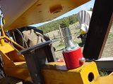
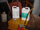
Oh almost forgot - I filled the Gear Box with 6.5 quarts of 85W90 gear oil. Rob, drilled, tapped and plugged (with nice brass plugs I might add) several fill (and drain) holes that are conveniently located. Rob made this thing so well and with such precision, there are no leaks!
I used one of those hand pumps attached directly to the jug of gear oil:
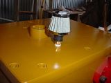
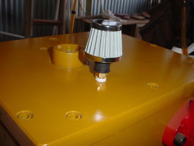
And added some *Bling* in the form of a chromed air vent:
Anyone want to offer some suggestions for the rear bracket? just take one of my photos and doctor it up so I can take a look at your idea.
thanks -
Larry
Thanks for following along on this project and for taking the time to post your comments and appreciation for all the work that Rob and I put into this.
And a very special thank you to Rob for all the precision machine work and fabrication. Without Rob's expertise and willingness to tackle this undertaking, all this would not have been possible.
This is not the end to this project by any means, as I still have the rear support bracket to fabricate. Then theres the matter of real field testing. Please look forward to some videos of it in real world action.
Rob - I took off those eye bolts and installed the SHCS. Do you want the eye bolts back?Rob - Don't forget to replace the eye bolts with those spare socket head cap screws. Although, I didn't think about it, but since I put nuts on the eye bolts, I guess you could leave them on if you wanted?
Oh almost forgot - I filled the Gear Box with 6.5 quarts of 85W90 gear oil. Rob, drilled, tapped and plugged (with nice brass plugs I might add) several fill (and drain) holes that are conveniently located. Rob made this thing so well and with such precision, there are no leaks!
I used one of those hand pumps attached directly to the jug of gear oil:

And added some *Bling* in the form of a chromed air vent:
Anyone want to offer some suggestions for the rear bracket? just take one of my photos and doctor it up so I can take a look at your idea.
thanks -
Larry
EddieWalker
Epic Contributor
Larry & Rob,
Congratulations and THANK YOU!!! You two have added an entire new level of what this site is all about. Not just tractors, or working the land, but combining two brilliant minds to from a friendship that is able to create something totally new and unique.
From an idea all the way through the process, it's been an a amazing adventure for me to follow along. I've learned more in this thread then I have in any others!!!!
The video came out realy cool, but now I'm looking forward to seeing what it's like to work it in the dirt.
Eddie