3RRL
Super Member
- Joined
- Oct 20, 2005
- Messages
- 6,931
- Tractor
- 55HP 4WD KAMA 554 and 4 x 4 Jinma 284
I'm with you all the way Scotty, it's nice to be "needed" again in my old age. Even nicer someone appreciates it too!scott_vt said:Mornin Rob & Larry,
Nice progress ! Im really enjoying this threadfor a couple of reasons really !
1st its really interesting !
2nd I think its great that so many people are interested in machining ! When I got into the trade 35 years ago, people would say, so what trade are you in ? And I would tell them toolmaker/machinist, and they would say "ohhh you do that"
Keep the posts and pics coming, Im feeling important again !
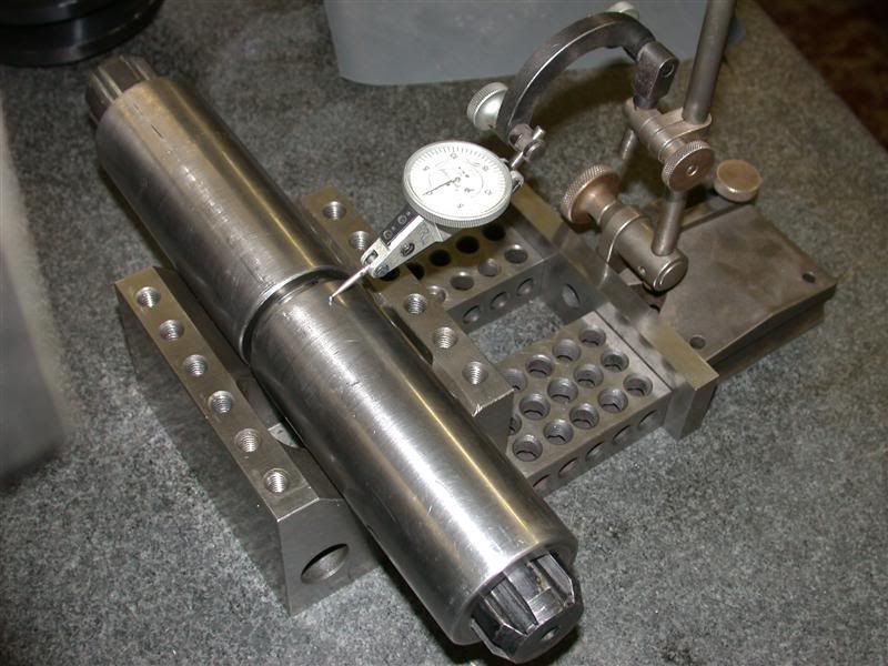
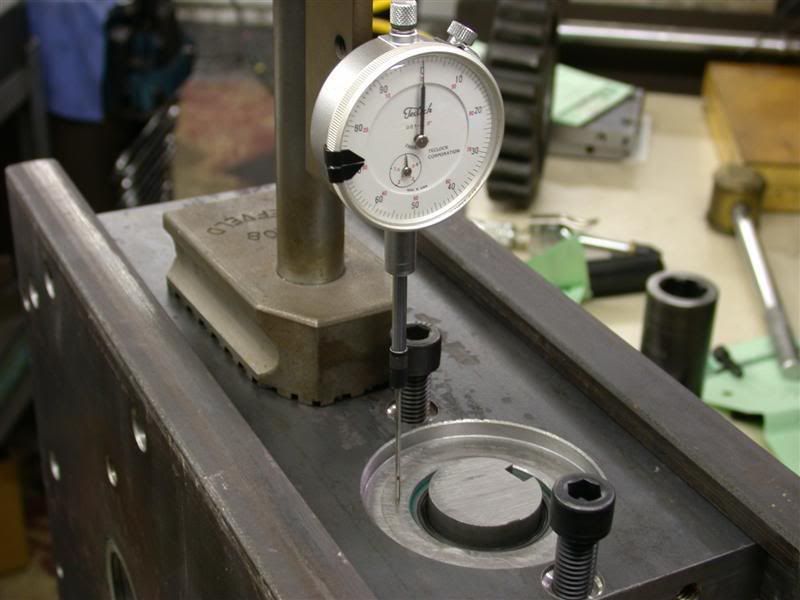
BTW, did you see that neat depth mic extension and clamps for it? It is exactly 1" tall and I can reach out 8" with it.
Thanks,