All right - here we go...
Got the
chipper put together yesterday. Thanks to Mark/DIYguy's online manuals, I got it put together properly. I think it would have taken be twice or thrice the 6 hours of assembly/setup/service time had I not had this resource. Here are my contributions to the knowledge base.
Assembly Notes:
-You need both metric (10mm, 13mm, 17mm) and SAE (1/2", 5/8", 3/4") wrenches and sockets.
-Your grease gun needs a flexible hose to get at the fittings, as access angles to the fittings is limited.
-To assemble and attach the base, the main unit needs to be lifted - I used the FEL and a chain hooked onto the top of the flywheel housing. This is one heavy piece of metal.
-For those who want to preassemble the cube-shaped base (made up of 4 pieces of steel), the front and back sides sit inside of the side pieces.
-I was missing 3 grease fittings and one set of nut/bolt. Further, most of the grease fittings are brass and one sheared off.
-A handful of chips found in the flywheel housing when the inspection plates were removed was evidence that it had been tested at the factory before it was shipped.
Feed Mechanism Notes:
I've been following the discussion about the feed roller driveshaft issues and decided to pull the assembly prior to any problems occuring and see if I could prevent them. I'm glad I did. Pictures are in the next 3 posts.
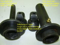
After removing the driveshaft, I bent each ball in its socket to its severest angle while pushing it in (to simulate spring tension) and rotated it through its full range of motion. The "fat" shaft was extremely smooth. The "thin" shaft was rough and "notchy" feeling. I concluded that the "notchy" motion was going the create an "in-and-out" chattering motion that would "jackhammer" against the retaining ring, eventually causing it to fail. I pried the retaining rings out using a screwdriver so I could compare the differences in the balls and sockets.
Both sockets were almost identical: each had a hemispherical bottom and were about the same depth. The "thin" one had several large chunks/shavings in the bottom corners that I pried/scraped out with a screwdriver.
The balls or "nubs" were strikingly different: the rough one was taller/longer and had 4 sharp edges where it was to contact the hemispherical portion of the socket. I ground the tip of the nub on a bench grinder to the same length as the good nub, but it was still kind of rough. I then smoothed the corners to mimic the corners on the good nub. Voila'! Smooth as silk.
After greasing them liberally but before installing the snaprings, I tested again and discovered each of the 4 possible positions of the nub in the sockets felt different with one position smoother than the other 3. I rotated the nub to the smoothest and snapped the rings back in.
I hope my little "re-engineering" helps keep my downtime to a minimum and helps those of you who have had problems.
Hookup and Usage Notes:
I only used it for about 15 minutes before I had to mow the grass, but -
WOW!!!! This thing eats wood.
-It is loud (use hearing protection) and throws stuff back out (face and eye protection.)
-If you have a PTO brake (like I do on my New Holland), I would highly recommend an overriding PTO clutch ($54.50 at Tractor Supply Co). The flywheel has an incredible amount of momentum and has great potential to damage the tractor's PTO brake. At 1500rpm, it took over 30 seconds for it to stop.
-The top link has to be extended out very far (almost to the end of travel), so if you've shortened your, you may need another. I could probably shorten the PTO driveshaft, but it is very short to begin with.
-The feed-roller disengagement linkage and the feel-roller lift bar make contact when either is used to their end travel. Not really an operational problem, but will cause paint wear in the long run.
I guess that's it. I'll post more a I discover it it.
Mark