FEL Grapple from Scratch W/ Lots-O-Pics

   / FEL Grapple from Scratch W/ Lots-O-Pics #31  
Scott,
I'm sure there are several milling machine models that come with 220v single phase out there. My recommendation would be to look up machinery sales places and find a used mill. With all the CNC equipment out there now, you could get a pretty good deal on a used model. Even on eBay. I'm just guessing, but for what your machining needs are, it doesn't have to be perfectly accurate. It just has to be beefy enough and have the right capacity for the work you will do. These are usually 3ؘ motors, but many types of phase converters are available...either static or dynamic. That's what I would look for. I have a whole garage full of 220v 3 phase equipment that I run off a 10hp rotary phase converter.
 
   / FEL Grapple from Scratch W/ Lots-O-Pics #32  
You can also take a look at GRIZZLY, just stay away from the "mill/drills" as they are a PITA! I know because I have one.

To go this route expect to spend about 3K to 4k to get setup with a decent machine and tooling.
 
   / FEL Grapple from Scratch W/ Lots-O-Pics #33  
Larry:

That's a great job. You and Rob should put it in a book.

I am intrigued with your use of the variable volume flow control. It appears you have a solenoid single selector valve in the inlet circuit to the flow control. Is that to insert it into the circuit only when the grapple is activated? A description (or even better, a diagram) of the circuit would be most appreciated.

Again, you are to be commended on a most professional job.
 
   / FEL Grapple from Scratch W/ Lots-O-Pics #34  
3RRL said:
Larry,
What a great thread!
Yeah, that's exactly what I meant. Now just squirt some grease in there and try it out. I just got home from camp and came across your thread tonight. You sure did a great job Larry....and didn't waste any time getting on it. Looks like it's coming together perfectly.

Scott and gmlf,
lol ... When am I supposed to fly out to your place? I would love to meet you guys! I'm ready to go, but it looks like Larry still need to finish his grapple first.:)

Rob, anytime is fine with me!! Right about now would be good timing for some lobster and blueberry cobbler, and maybe an adult beverage to quench the thirst after all the work we do! If you could just get me started on added additional remotes on my tractor! The mechanical side is fine, its the hydraulics that are killing me. I mean a simple log splitter circuit is OK, but this POCV stuff is frying my grey matter. Anyway, a great post and Larry is doing a great job, and your time in putting together a informative post is of great help, thanks much
 
   / FEL Grapple from Scratch W/ Lots-O-Pics
  • Thread Starter
#35  
Ductape said:
Larry,
A question from a guy on the outside looking in. Is there a reason you couldn't put the zerk in the end of the pin, where the set screw went? I would think that would keep you from having to remove it any time you wanted to pull the pin.......
Scott

Scott - Yea that's a good idea - The reason I didn't do that is because there are two holes through the head of the pin for the handle. Grease would have come out those holes, unless I cut the head of the pin off past those holes, Or counter bored deep into the pin. I wanted to keep the machining on the pin modification to a minimum so I settled on putting the grease fitting in the middle.

I see Rob's answered your machine question, which is a good thing because he's 1000% more qualified than I.

Larry
 
   / FEL Grapple from Scratch W/ Lots-O-Pics #36  
Larry,

You and Rob really need to get together and spend a year chronically all your projects for a book. With the pictures and details that you have, it's must reading for all of us!!!!!

Eddie
 
   / FEL Grapple from Scratch W/ Lots-O-Pics
  • Thread Starter
#37  
Farmerford said:
Larry:

That's a great job. You and Rob should put it in a book.

I am intrigued with your use of the variable volume flow control. It appears you have a solenoid single selector valve in the inlet circuit to the flow control. Is that to insert it into the circuit only when the grapple is activated? A description (or even better, a diagram) of the circuit would be most appreciated.

Again, you are to be commended on a most professional job.

Farmerford - thank you for the compliments and your question.
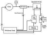
The electric Solenoid which operates the grapple is attached to the Excess flow output of the variable divider. Here is a basic hydraulic schematic of the system. The diagram is in simple terms that are (hopefully) easy to understand.
Click on image for full size:


I also have Top & Tilt Tilt (TTT) plus two remotes, basically the entire circuit is in series (except the grapple - it's down stream off one end of the Divider). When I'm not using the grapple, I can adjust the divider for max flow through the FEL valve if I want / need more flow. Flow is not a problem though, as I have ~ 9.5 GPM available at rated RPM.

Larry
 
   / FEL Grapple from Scratch W/ Lots-O-Pics
  • Thread Starter
#38  
EddieWalker said:
Larry,

You and Rob really need to get together and spend a year chronically all your projects for a book. With the pictures and details that you have, it's must reading for all of us!!!!!

Eddie

Eddie - that is a fine compliment and very flattering indeed, thank you so much.
Writing a book :confused: hum, I don't know, sounds an awful lot like work to me. Rob ? What do you think? Can we become rich & famous on a tractor / implement mod book?

Larry
 
   / FEL Grapple from Scratch W/ Lots-O-Pics
  • Thread Starter
#39  
OK back to the Grapple from scratch -

I still messing around with pins :rolleyes:
I figured as long as I made those fancy grease-able pivot pins I better lock them in place so the pins won't rotate inside the brackets.

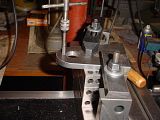
First was to drill through the pin shoulder & bracket:


Then tap the hole:


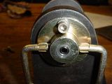
Then screw in a stainless steel socket head cap screw (SHCS)


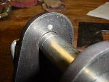
The screw is only 1/2" long so it's flush with the other side of the bracket:


OK so now the pins will be "locked" in place, no rotating, no falling out, no lynch pins, no retainer chains & hey I can remove the handles too. This will make it nice and clean - nothing that anything can catch on.

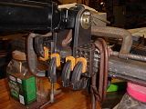
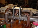
I hope to do some welding soon, so better get busy clamping things together. 1-2-3 blocks came in real handy to get the cylinder mount bracket nice and square onto the 2" square cross tube:


After using a few clamps to get the blocks square to the tube, a few more clamps were used to clamp the brackets to the block:


Once everything was square and tightened down, all but the essential clamps & 1-2-3 blocks were removed:


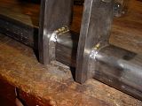
I welded the front cylinder bracket to the 2" square x 1/4" wall cross tube.


It came out nice and square and just enough room to fit the cylinder clevis without binding.
Well that's it for tonight.


Larry
 
Last edited:
   / FEL Grapple from Scratch W/ Lots-O-Pics #40  
Larry,
I am pleased to see you making great use of all your machine tools. The set-ups and clamping positions are perfect, insuring squareness. That boring job came out very very good too! I should have mentioned to you in order to get a hole right on size, leave the dial setting alone after the first pass and re bore to cut out any "spring" accumulated in the boring bar. Then move it out for the next pass and do it the same way. You can get to within .0002" that way.

Anyway, it's a slower process than drilling, but that's what the boring head is for. It sure does look like the shape and clearances designed matches the shape of the bucket dimensions you gave me. That was the only part I was worried about. I have the tendency to design too close...too perfect, know what I mean? But from these photos it looks like I got it right with plenty of clearance... and it will work.

Your next step will be to get the distances between the cylinder pivot on the bucket and the jaws correctly mounted. I believe I gave you enough dimensions to mount them. I tried to make them parallel to surfaces you can measure from. However, you still need to check with the actual cylinder, since on some cylinders, the actual travel is slightly different than advertised.

The other cross-bracing is just that...cross bracing for strength. Their exact position is not nearly as critical as the pivot locations. Just be sure those other cross braces don't interfere with the cylinder body at any point during extension and retraction.

One last thing...
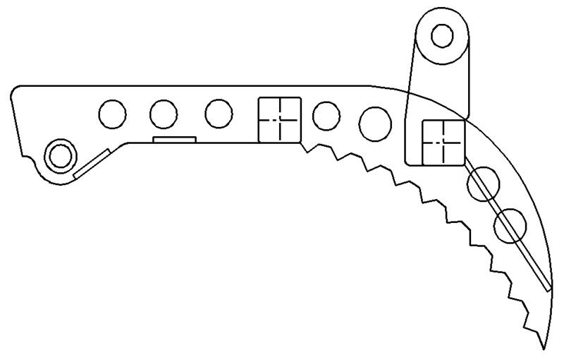
I thought of drilling a few "lightning holes" in the grapple jaws themselves to remove some weight but not strength. They are not necessary nor will they affect the strength of the jaws. So if you are interested call me. They are like the holes in your 1-2-3 blocks, except I would make them リ1-1/2" and リ1-1/4" in front and behind where the pivot tube connects to the jaws...space equally.
Something like this:


I don't think you need them at all, that's why I didn't draw them in the first place. But thought I'd throw it out there to make the jaws "look" even more high tech before you welded them. On the other hand, I did not want to detract from the traditional rural grapple look either ...the choice is yours.

You are doing a terrific job. I have a feeling your grapple project will turn out great. I'm so glad you like the design.
 

Tractor & Equipment Auctions

2022 CASE TV370B SKID STEER (A51242)
2022 CASE TV370B...
1981 Case 245 2wd tractor with Rotary cutter (A51039)
1981 Case 245 2wd...
Pallet Fees (A50774)
1999 INTERNATIONAL PAYSTAR 5000 TANDEM AXLE DUMP TRUCK (A51222)
1999 INTERNATIONAL...
2004 Dodge Dakota Ext. Cab Pickup Truck (A50323)
2004 Dodge Dakota...
2017 Ford F-450 Crew Cab Knapheide Service Truck (A49461)
2017 Ford F-450...
 
Top