Glow Plug Timer control units

   / Glow Plug Timer control units #1  

SG51Buss

Member
Joined
Jan 20, 2015
Messages
37
Location
Fredericksburg, Texas
Tractor
New Holland TC35
The glow plug indicator lamp on my New Holland TC35 Boomer would occasionally come on, and now it just stays on.
According to the helpful threads in this forum, the cause is a faulty glow plug timer unit:

http://www.tractorbynet.com/forums/new-holland-owning-operating/110076-glow-plug-problem.html

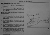
Pulled the unit, bench tested it per this procedure, and sure 'nuff, it's bad.
TC35-TimerTest01.jpg TC35-TimerTest02.jpg
 
   / Glow Plug Timer control units
  • Thread Starter
#2  
The replacement timer was going to run me close to $120 from the local dealer.
So, I opted to get a couple of the Kubota timers off eBay, for $35.

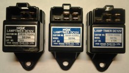
Now I've got 3 timers.
3-GlowPlugTimers.jpg
 
   / Glow Plug Timer control units
  • Thread Starter
#3  
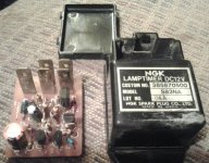
Let's see what's going on in here.
The boxes are easy to open, just pry off the back.
TC35-GlowPlugTimer02.jpg

This is where the surprises appear. The printed circuit boards inside the boxes are all different.
The board inside my original timer box doesn't even match the model number labeled on the box.
This is what I found:

New Holland P/N SBA385870500 Model# S83NA, Lot#04A - contains S81NF-1
Kubota P/N 15694-65992 Model # S81NL, Lot#07C - contains S81NL-1
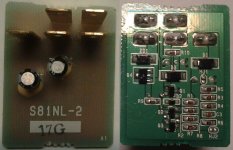
Kubota P/N 15694-65992 Model # S81NL, Lot#17H - contains S81NL-2

The Kubota timers are supposedly interchangeable with New Holland's SBA385870301, the faster timer.

Why my box has a different board, I haven't a clue.

So, I've decided to reverse-engineer the circuits, to see how they work, if they can be diagnosed, and if they're repairable.
 
   / Glow Plug Timer control units
  • Thread Starter
#4  
This is what the NGK S81NF-1 LampTimer PCB looks like:
(Please ignore the unsoldered transistor)
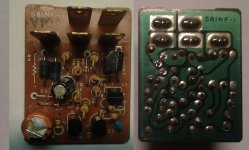
NGK-S81NF-1-pcb.jpg

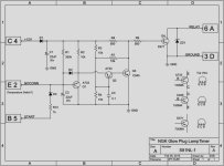
This is the NGK S81NF-1 LampTimer circuit schematic:
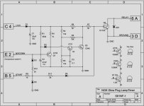
NGK-S81NF-1-sch.jpg


General description:

The region around transistor Q1 is the timing circuit, defined by charging rate of the resistor/capacitor pair R1 & C2.
Initially, their voltage is low, so the base of Q1 drains into this R/C pair, pulling the output of the pull-up resistor R4 low. After sufficient time has elapsed for C2 to charge, Q1 is turned off, and the output of this timing section (emitter of Q1) goes high, triggering the sense/latch section.
Pin #2 (or E) goes directly to Q1's base. It isn't used on the New Holland Boomer schematics. But, I found a Kubota schematic showing that pin wired to a temperature switch, so it would influence the timer section. Which way, I don't know.

The region around transistors Q2 & Q3 is the sense/latch circuit.
Q2 will only pass current to Q3's base when its emitter voltage (controlled by the output of the timing section) goes higher than its base voltage (defined by voltage dividers R2 & R3). When that occurs, current is passed to the base of Q3, turning it on.
Q3 is initially off, allowing its collector voltage to be high, which keeps driver transistor Q4 turned on. When Q3 turns on, it pulls its collector voltage low, pulling voltage from Q4's base, turning it off. Q3 also drains current through R5, pulling the threshold voltage of Q2's base low, forcing it to latch 'on', keeping Q3 turned on, which keeps Q4 turned off.

The transistor Q4 is the output relay driver.
Initially, it is turned on, because it's receiving current through the R6/R7 resistor pair. When Q3 turns on, it sinks current away from the R6/R7 pair, turning Q4 off.
Q4 is the grounding driver for the Glow Plug relay. When Q4 is 'on', the glow plugs and indicator lamp receive power. Q4 is protected from the relay's inductive kickback by zener diode ZD1. I measured the resistance of the glow plug relay solenoid coil, and got about 72 ohms. That means that Driver Transistor Q4 will need to sink about 150-200 mA current to energize the relay. The Q4 D1153 Darlington transistor is rated for 1.5 amps, plenty for this.

When the starter is engaged, current rushes through R9, and does 2 things.
First, current rushes through R10/D3 to charge the timer cap C2, ending its cycle.
Second, current rushes through R11/D4 to the base of Q4, forcing it to come (or remain) 'on', overriding the output of the sense/latch section.
This causes the glow plugs to come (or remain) 'on' during starting.

Failure mode:
Occasionally, the glow plug relay will energize, or just remain 'on', as seen by the indicator lamp. When I bench-tested my timer, I found a residual/varying 3-4 volts at Q4's base, keeping it turned 'on'. So, either the Q2/Q3 latch circuit failed, or timer Q1 shorted. I'm not sure if the current inrush from the starter input may be damaging these sections. The timer capacitor C2 (big orange thing) is only rated for 10 volts. Maybe it's underrated and failing.
 
   / Glow Plug Timer control units
  • Thread Starter
#5  
This is what the NGK S81NL-1 LampTimer PCB looks like:
(For the Kubota)
NGK-S81NL-1-pcb.jpg

This is the NGK S81NL-1 LampTimer circuit schematic:
NGK-S81NL-1-sch.jpg


General description:

The NGK S81NL-1 LampTimer is quite similar to the previous NGK S81NF-1, with a few differences:

1. The timers R1/C2 are different, a faster timebase. C2 is now rated for 25v.
2. Some of the designators for the resistors have changed, not important here.
3. The R8/R9 current control resistors are much smaller, Q3 will need to sink about 20mA now.
4. Driver transistor Q4 is now a regular NPN, with half the current rating. Still enuff though.
5. Big difference is the 'start' circuit. This one doesn't turn on the glow plugs during start.

Bench test:
Ran the lamp test on the unit, found that it stays on for 6 seconds.
Then the lamp flickers rapidly for another 1-2 seconds before staying off???
This could wreak havoc on the glow plug power relay, needs further investigation...
 
   / Glow Plug Timer control units
  • Thread Starter
#6  
This is what the NGK S81NL-2 LampTimer PCB looks like:
(For the Kubota)
NGK-S81NL-2-pcb.jpg

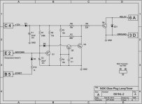
This is the NGK S81NL-2 LampTimer circuit schematic:
NGK-S81NL-2-sch.jpg


General description:

This NGK S81NL-2 LampTimer is functionally similar to the previous NGK S81NL-1, with some big differences:

1. The Printed Circuit Board now uses Surface Mount technology. Harder to fix.
2. As such, only the resistor values can be read. No discernable markings for the diodes and transistors.
3. The designators for the components are the same. Handy, but not important here.
4. The R8/R9 current control resistors are now much larger, Q3 won't need to sink as much current now.
5. The latch drain resistor R7 is much smaller now. Q2's base will be aggressively pulled low.


Bench test:
Ran the lamp test on the unit, found that it stays on for 5 seconds.
The lamp goes out quickly without any flickering.
 
   / Glow Plug Timer control units #7  
Well now THAT was interesting


I also have a NGK glow plug timer on my Yanmar built JD. I searched numerous electronic parts distributors for a replacement one with no luck

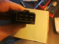
This one is even different yet S83NT-O1A and it has 6 blades.

0208150733-00.jpg


And according the shop manual schematic the Deere starting circuit also energizes the glow plug when the key switch is turned to start independent of the module operation. By overriding the starting circuit using a safety relay cutout switch (I pull out my dash mounted PTO switch) and holding the key I can activate my glow plugs for as long as I need.

When my module failed it caused a steady current draw and the charging system didn't operate right.

So I just unplugged it

It is about $90 part from Deere. Still I would like to replace it for less.
 
   / Glow Plug Timer control units #8  
Interesting, there's about 10 bucks of parts in there.
DFB, open yours up like SG51Buss did, we can take a look inside,
you could always bring it to a "computer", "TV", repair shop for an estimate to replace the defective parts.
Theres not much to them, I figure around $25 bucks to fix it.
 
   / Glow Plug Timer control units #9  
Interesting, there's about 10 bucks of parts in there.
DFB, open yours up like SG51Buss did, we can take a look inside,
you could always bring it to a "computer", "TV", repair shop for an estimate to replace the defective parts.
Theres not much to them, I figure around $25 bucks to fix it.

Yep $10. of parts but that is normal factory mark ups to be a profitable enterprise.
Rule of thumb is 10X cost of components = retail $
 
   / Glow Plug Timer control units #10  
Althought I am clueless about electronics, I have great pleasure to follow your thread.
You have just given out a great idea to get some electronics repaird at a fraction of the new part price: Go to a TV/Computer repair shop to get it fixed! Thank you.
In this regard you help other electronics clueless members!:thumbsup::)
 

Tractor & Equipment Auctions

2003 TRAILMOBILE 32FT DRY VAN (A43004)
2003 TRAILMOBILE...
2013 UTILITY 53X102 DRY VAN TRAILER (A43004)
2013 UTILITY...
2012 UTILITY 48X102 REEFER TRAILER (A43004)
2012 UTILITY...
2016 Ford Explorer AWD SUV (A44572)
2016 Ford Explorer...
2012 MACK GU713 TRI AXLE DUMPTRUCK (A43004)
2012 MACK GU713...
2014 UTILITY 53X102 DRYVAN (A43004)
2014 UTILITY...
 
Top