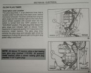
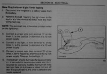
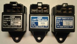
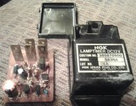
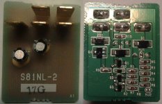
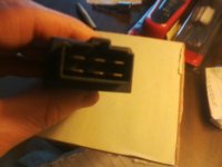
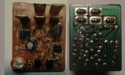
This is what the NGK S81NF-1 LampTimer PCB looks like:
(Please ignore the unsoldered transistor)
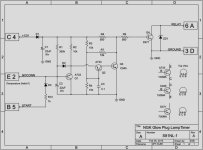
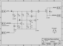
This is the NGK S81NF-1 LampTimer circuit schematic:
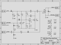
General description:
The region around transistor Q1 is the timing circuit, defined by charging rate of the resistor/capacitor pair R1 & C2.
Initially, their voltage is low, so the base of Q1 drains into this R/C pair, pulling the output of the pull-up resistor R4 low. After sufficient time has elapsed for C2 to charge, Q1 is turned off, and the output of this timing section (emitter of Q1) goes high, triggering the sense/latch section.
Pin #2 (or E) goes directly to Q1's base. It isn't used on the New Holland Boomer schematics. But, I found a Kubota schematic showing that pin wired to a temperature switch, so it would influence the timer section. Which way, I don't know.
The region around transistors Q2 & Q3 is the sense/latch circuit.
Q2 will only pass current to Q3's base when its emitter voltage (controlled by the output of the timing section) goes higher than its base voltage (defined by voltage dividers R2 & R3). When that occurs, current is passed to the base of Q3, turning it on.
Q3 is initially off, allowing its collector voltage to be high, which keeps driver transistor Q4 turned on. When Q3 turns on, it pulls its collector voltage low, pulling voltage from Q4's base, turning it off. Q3 also drains current through R5, pulling the threshold voltage of Q2's base low, forcing it to latch 'on', keeping Q3 turned on, which keeps Q4 turned off.
The transistor Q4 is the output relay driver.
Initially, it is turned on, because it's receiving current through the R6/R7 resistor pair. When Q3 turns on, it sinks current away from the R6/R7 pair, turning Q4 off.
Q4 is the grounding driver for the Glow Plug relay. When Q4 is 'on', the glow plugs and indicator lamp receive power. Q4 is protected from the relay's inductive kickback by zener diode ZD1. I measured the resistance of the glow plug relay solenoid coil, and got about 72 ohms. That means that Driver Transistor Q4 will need to sink about 150-200 mA current to energize the relay. The Q4 D1153 Darlington transistor is rated for 1.5 amps, plenty for this.
When the starter is engaged, current rushes through R9, and does 2 things.
First, current rushes through R10/D3 to charge the timer cap C2, ending its cycle.
Second, current rushes through R11/D4 to the base of Q4, forcing it to come (or remain) 'on', overriding the output of the sense/latch section.
This causes the glow plugs to come (or remain) 'on' during starting.
Failure mode:
Occasionally, the glow plug relay will energize, or just remain 'on', as seen by the indicator lamp. When I bench-tested my timer, I found a residual/varying 3-4 volts at Q4's base, keeping it turned 'on'. So, either the Q2/Q3 latch circuit failed, or timer Q1 shorted. I'm not sure if the current inrush from the starter input may be damaging these sections. The timer capacitor C2 (big orange thing) is only rated for 10 volts. Maybe it's underrated and failing.
