LandPlane,, My DIY

   / LandPlane,, My DIY
  • Thread Starter
#21  
Nice find. If you don't mind... How much was the song?

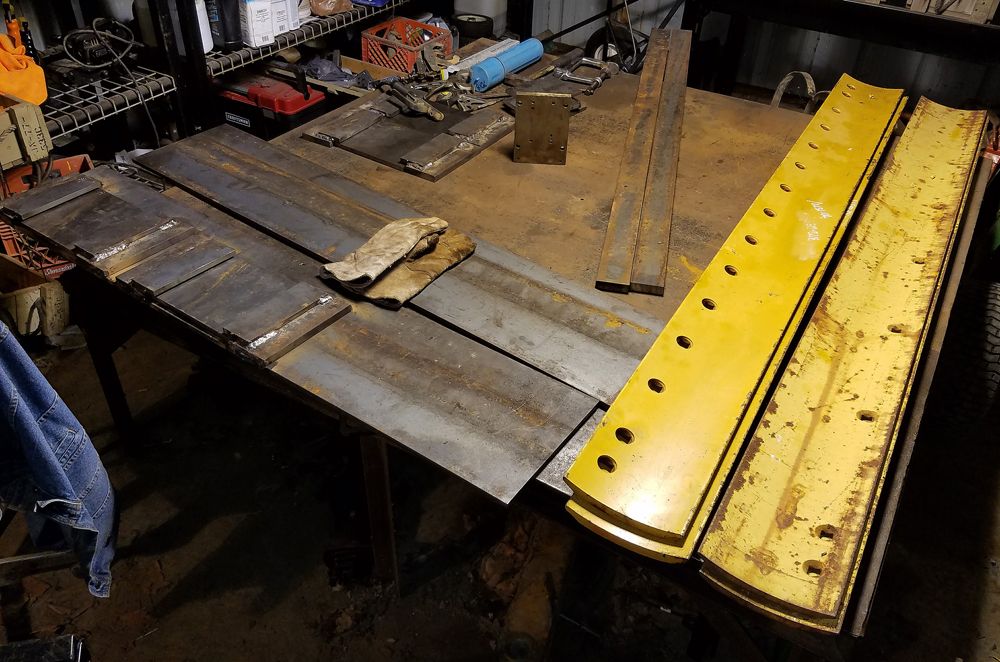
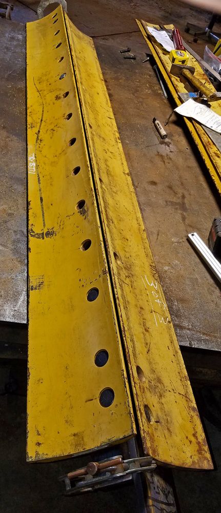
All four blades are 8" wide,, and are 126 pounds each for the 3/4" ones.
The 5/8" ones are about 115 pounds each.
I paid $170 total for all of them.
That ends up being 482 pounds,,, at about 35 cents a pound. :cool2:

Normal price for the 3/4" ones is $169 each.

As far as the paint, the nicely painted ones have the paint missing in the mounting holes.
Once something has been mounted, they do not sell it as new.

A customer probably requested that their new motor grader have a different cutting edge.

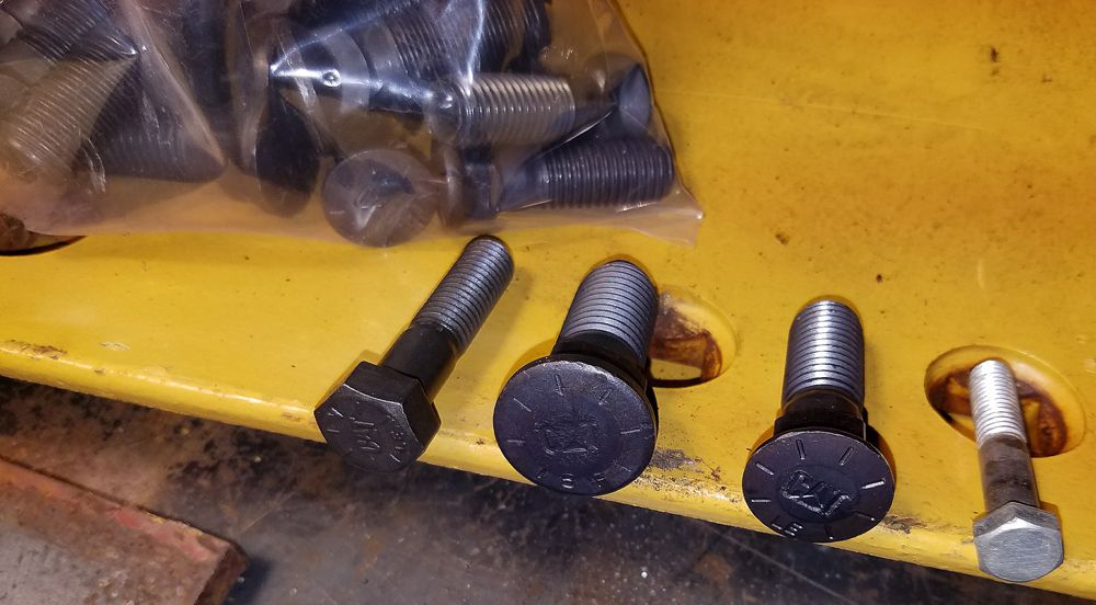
I looked up the part number of the 3/4" one, the CAT website showed typical applications.
it is the cutting edge for a current production motor grader with a 14 foot blade.
 
   / LandPlane,, My DIY #22  
If you go back look for blades with center mounting bolts. If you find these you can flip them over and get twice the life out of one blade.

Another reason that I used what I had.

IMG_20160721_171105_552_zpsb5xi4h6q.jpg
 
   / LandPlane,, My DIY #23  
If you go back look for blades with center mounting bolts. If you find these you can flip them over and get double life out of one blade.

Another reason that I used what I had.

IMG_20160721_171105_552_zpsb5xi4h6q.jpg


I built my lpgs in 2009 and use it a lot in my business. Mine has the center mounting to reverse them but after 8 years there is still no need to.
 
   / LandPlane,, My DIY #24  
CADplans I would recommend mounting the grader blades to 6x6x1/2" angle iron. The added height will allow you to carry more material to fill in dips.

Those are nice blades, I bought my first set from CAT and my second set for the smaller plane from Deere. All of them have held up very well.
 
   / LandPlane,, My DIY #25  
I built my lpgs in 2009 and use it a lot in my business. Mine has the center mounting to reverse them but after 8 years there is still no need to.

Life depends a lot on how hard it is, just saying you can double it, for blades, if you pick the right one.
 
   / LandPlane,, My DIY
  • Thread Starter
#26  
Thanks for the comments, and input guys!! :thumbsup:

My LP will be used for personal use,, I doubt it will ever show wear on these blades, based on my needs.

I thought the sides of the LP were massive,,, the blades will overwhelm the entire build.

weld%20table_zpsxsgwjmu7.jpg


The blades sure overwhelmed my weld table!! :laughing:

The center two bolts are for the grader blades.
The bolt on the right is a 3/8" dia bolt for scale.
The bolt on the left is a 1/2" CAT bolt,,, the head seems to be about twice as thick,,,

BoltsA_zpsxxfvnad8.jpg
 
   / LandPlane,, My DIY #27  
When I mounted my blades I am pretty sure I used 5/8" plow bolts. Is that what you have in your picture?
 
   / LandPlane,, My DIY
  • Thread Starter
#28  
When I mounted my blades I am pretty sure I used 5/8" plow bolts. Is that what you have in your picture?

The smaller bolt is 5/8", the larger one is 3/4"
I took a pic while drilling a 3/4" hole in a 1" thick bar yesterday,,,

drill%20hole_zpssqr7y7sv.jpg
 
   / LandPlane,, My DIY
  • Thread Starter
#29  
I figured out how I wanted to mount the front blade, then found and cut the steel.
Next, there was a LOT of hole drilling,,, I have a pretty good size Amazon box full of drill chips :D
The front blade assembly is ready to weld into the frame,,,

Front%20Blade_zpsh6gld47t.jpg


This blade assembly is 13 inches wide,,, there may not be a need for a second blade.

I will have the frame ready for a second blade,,,but,,
I will definitely try the land plane with just one blade before adding the second.

The blade assembly is massive,, the assembly in the pic weighs over 300 pounds.
I would bet there are complete land planes on the market that only weigh 300 pounds total.

The strength of this assembly is also incredible.
I have no concern that the assembly will easily stop my 60 HP tractor.
The blades, are not only very thick tool steel, but, they are heat treated, also.
If you hit the blade with a hammer, they ring like a bell.

If I do not use all of the blades in the land plane,,,
I think I will cut up the remainder and make the loudest wind chime,,, EVER!!:laughing:
 
   / LandPlane,, My DIY #30  
Are you building this with back to back blades as in your picture?
 
   / LandPlane,, My DIY
  • Thread Starter
#32  
Today, I welded the two side assemblies. Both left and right are identical.
Since the movable mounting plates are offset,
the the offset will cause the left front of the blade to be 22" back further than the right.
If my TRIG still works,, the grader blade will be at about a 15 degree angle,,
(84.5" wide,, 22" offset, is that ~15 degrees?)


Side%20Assembly_zpsxyntpul3.jpg


The had two materials I had for runners was 1/2" X 6" and 1" X 3". I went with the 1X3.
I figured there may be a time I will need the runners to "dig in", that would never happen with 6 inch wide runners.

The hope is that I will be able to move the two guillotine like plates up or down to adjust the grader blade height.
I say "HOPE", because it may be tricky welding the assembly together accurately enough that the plates do not bind.

The adjustment range will allow the blades to be positioned from one inch above the runners,
to several inches below the runners. Would I EVER want the blades to be higher than 1" above the runners?? :confused:
My initial setting will have the blades even with the runners.
That seems to be typical of others land planes.

Next, I will weld in the three 84.5" tubes that space the sides apart.
 
   / LandPlane,, My DIY #33  
Would I EVER want the blades to be higher than 1" above the runners?? :confused:

I made mine so that I could (hopefully) spread materials. It works pretty well, and so what if you don't use this feature. How do you plan on changing the depth? The pic. is from putting in a lawn & spreading topsoil at about 3". It moves from about a 1" cut to close to a 4" above "spreading" depth.
 

Attachments

  • DSCN3660.JPG
    DSCN3660.JPG
    281.2 KB · Views: 750
   / LandPlane,, My DIY
  • Thread Starter
#34  
I made mine so that I could (hopefully) spread materials. It works pretty well, and so what if you don't use this feature. How do you plan on changing the depth? The pic. is from putting in a lawn & spreading topsoil at about 3". It moves from about a 1" cut to close to a 4" above "spreading" depth.

Very interesting!! :thumbsup:

I will see how high I can get the blade, I may run out of adjustment when the blades are 3" above the runners.
 
   / LandPlane,, My DIY #35  
I punched the carriers for my blades and side plates for adjustment from 1/2" above grade to an inch and a half below (with rippers that can go negative 3" if needed).

I welded the angle iron that holds the blades at over 45 deg so I can backup to spread material without cutting, it pushes high down while riding on the skids.

Haven't moved them from 1/2" negative cutting forward yet.
 
   / LandPlane,, My DIY #36  
You can pre drill to add 2x4 lumber or whatever to the skids to spread a layer of mulch or top soil. Just need a separate tractor/fel to keep the lpgs loaded with material as you move along.
 
   / LandPlane,, My DIY #37  
That remindes me, I remember a landscapeing co. that put in lawns for the builders in a large subdivision. He bolted on long 7'-8' oak or locust 4x4's or so as skids to his regular box blade. This was 20 years ago and may have been the first so called "land plane" out there.:laughing: It did work well and at the time, I just wrote it off as hillbilly engineering.:confused3:
 
   / LandPlane,, My DIY
  • Thread Starter
#38  
I was drilling the holes for the 3 point hitch attachment (one inch,, I could not find the 7/8" bit :laughing: )
and I took a pic.
I thought some of you might be wondering why I have a clamp permanently bolted to my drill press vise.

Drill%20Clamp_zpsl3kgenih.jpg


The clamp applies down pressure on the parts, when I am drilling multiple parts at one time.
Hot rolled steel varies enough in width, that the vise can not hold all the parts firmly.

The clamp insures that one or more of the parts do not start walking around.

The vise is a "self centering" type. That makes setup easier when you are drilling a bunch of holes in the center of a group of parts.
The drill will stay at the center of a part, whether it is 2, 3, 4, 6, etc inches wide,
both the front and rear vise jaws move as the handle is rotated.
 
   / LandPlane,, My DIY #39  
Hot rolled steel varies enough in width, that the vise can not hold all the parts firmly.

Drop a strip of cardboard or wood between the moving jaw and parts. They will still be consistently spaced by the rear jaw and the strip will compress with the long ones and hold the shorter ones.

You can also run into the same issue in your saw. You can clamp them all together or if you have a welder handy tack the "drop" ends together so they don't move realitive to one another as they are fed.
 
   / LandPlane,, My DIY
  • Thread Starter
#40  
Last second design change,,,
I decided to add a bit of angle adjust-ability to the top link connection.
I can use the mechanical link shown, or a hydraulic cylinder,,,

Top%20Link%20Conn_zpsqr3unlyi.jpg


I am trying to get all the welding done on the frame before I add the grader blades.
Hopefully, I will not have any distortion later that would inhibit the up and down movement of the grader blades.

Standing_zpsvcfqojer.jpg
 

Marketplace Items

2338 (A60432)
2338 (A60432)
Ford 8340 (A53317)
Ford 8340 (A53317)
2019 BOBCAT T450 SKID STEER (A60429)
2019 BOBCAT T450...
2017 CATERPILLAR 305E2 CR EXCAVATOR (A60429)
2017 CATERPILLAR...
2021 SANY SY265C LC LONG REACH EXCAVATOR (A59823)
2021 SANY SY265C...
TOOTHED BUCKET ATTACHMENT FOR MINI EXCAVATOR (A58214)
TOOTHED BUCKET...
 
Top