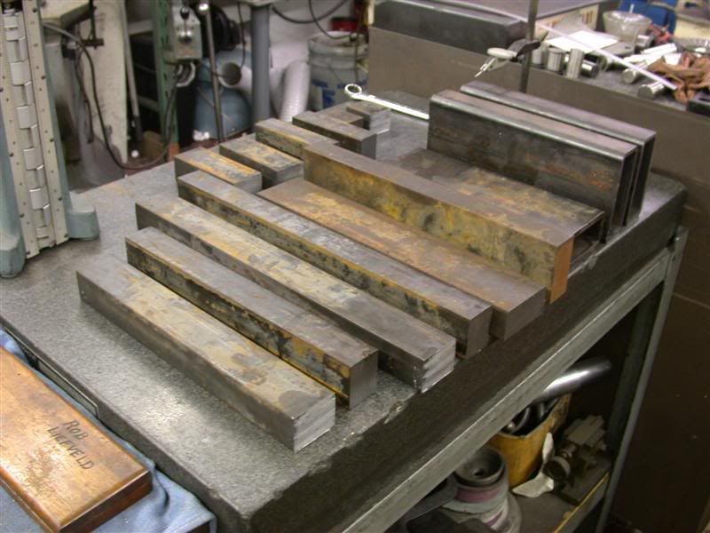
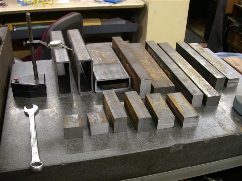
MODIFY BRUSH HOG SOME MORE

   / MODIFY BRUSH HOG SOME MORE
  • Thread Starter
#61  
Well thank you Jake. LOL ... I know John expects a bit more from what he's seen in the past. I'll leave the electronics up to Larry of course.

I know this is not the most exciting project and probably not very useful since I only mow like 2 times a year right now. But when I move up there I will have a couple more meadows to mow than I do now. It will be a fun gadget to run.

The plasma cutting sure made this a lot better looking linkage than what I first had in mind. Thanks again Larry for giving me all that stuff. Using all scrap steel and slitting that stuff to make it useful is time consuming. But I've got nothing else to do anyway. I ended up busting 3 of those slitting saws, but got all of it done except the pieces that will be welded to the RC body. But all the stuff for this frame and linkage is cut now.

I finished making the spacers for the linkage. They are sets that will fit between all the shapes that were plasma cut.


I also cut and ground the hardened bushings, then welded the links together using the spacers. The spacers also provide rigidness against twisting. I welded them up with the pins and bushings in place and clamped up to keep them in line. They are like giant links for a giant chain. They are very solid now.

 
   / MODIFY BRUSH HOG SOME MORE
  • Thread Starter
#62  
This is part of the frame that will be welded to the rear of the RC. I got a 3" cylinder with a 1-1/2" diameter rod for extra strength.


I am not going to weld up the front of the cylinder mount until I bring it up to the property. I need to mount the frame onto the RC and then position the front cylinder mount to give me the wheel travel I want. I'll have to check it there to see, by moving the cylinder in and out. Then I'll weld that part last.

Here are the links all pinned together. I still have to cut off the hardened pins to length and drill them for grease fittings. If I remember right, they are case hardened so I can tap the holes after getting through the hardened surface. (I hope). There is also a close up of the linkage. I have not cleaned up my welds yet because I wanted to post some progress before leaving for camp.


I got an email from Discount hydraulics that they just now shipped my hydraulic fittings that I ordered 2 weeks ago. :mad: Swell... they have done that every time now that I've ordered from them, so I'm not too happy about that. Just as well though, since I won't have time to finish what I need to bring up anyway. I still have to do the above and also make the bushings for the second wheel. Then make a frame of some sort to attach the wheels to the front of this thing. I won't have enough time before we leave. But at least you can see where I'm at.
 
   / MODIFY BRUSH HOG SOME MORE #63  
3RRL said:
... I know John expects a bit more from what he's seen in the past. I'll leave the electronics up to Larry of course.

I probably speak for many of us in the cyber tractor world when I say, The vision, talent, skills, teamwork exhibited by the dynamic duo of Rob and Larry are stunning. Only exceeded by your ability to share and explain what you did and how you did it.


Thanks~!

jb


P.S. - I was just kidding about the laser interferometry, radar feedback could also be used! Maybe for a follow up project, you two could invent an anti-gravity generator to save some $$ on wheels?
 
   / MODIFY BRUSH HOG SOME MORE #64  
3RRL said:
This is part of the frame that will be welded to the rear of the RC. I got a 3" cylinder with a 1-1/2" diameter rod for extra strength.

How heavy is it?
 
   / MODIFY BRUSH HOG SOME MORE
  • Thread Starter
#65  
Rowski,
I haven't weighed these parts but your assumption is correct, there will be added weight to the hog. Remember I am eliminating the long triangular wheel mount and replacing it with this one, so there will be a net result. I'm guessing about 120 to 150 lbs. in steel linkage and body reinforcement. Closer to 200 lbs when you consider the new wheel. However, it will be distributed over 2 wheels instead of one when in use.

John,
Your comments always put a big grin on my face. They add another dimension to these projects. This is a fun project and it's great to see someone else get a kick out of it (besides me).:) LOL ... I see all those drugs you took years ago are finally starting to pay off.:D
 
   / MODIFY BRUSH HOG SOME MORE #66  
Rob,

Not drugs, It's from pounding my head against the wall until all my problems go away. Or I fall down unconscious, works either way, but as you have noted the after affects are becoming more predominate.
 
   / MODIFY BRUSH HOG SOME MORE #67  
dam you never do anything light weight do ya! ;)

i want to see mounted pics!
 
   / MODIFY BRUSH HOG SOME MORE
  • Thread Starter
#68  
LOL ... It's dragging along so it must be heavy? :)
I just got back from vacation and the fittings arrived. I think I can build the hard lines for the cylinder and DPOCV now. I should be able to get a little more done on it for the pins and wheel mounts, but my log home project is moving along and requires me to get some things lined up this week. I will post more pics later.
 
   / MODIFY BRUSH HOG SOME MORE #69  
Rowski said:
nice idea.

I like the drawings... some day I would like to learn how to design on a CAD type program.

There are plenty of programs out there. some free some not It depends on what you are trying to do. I know there is some free 3d animation programs but not sure how close to cad use they get. I havent had time to mess with much the last fiew years :/


Some nice work there guys. If i could only get to start using my tractor i might find some cool projects to compete with yourse ;)

Per question earlier there IS a poormans way of auto leveling the unit it would not like being beaten though... but may still work. off the front end you have a 3' or so leader it pushes and pulls a valve which would raise and lower the front end. I doubt it would be horibaly practicle but it would work... 1 or 2 feelers set to end about where the rear tractor tires are and level with the deck a valve that would allow a gentle to emergency up and a slow down... you could rig it so that 2 feelers could work at the same time. If you put electronics in to it you could have front and rear mower cillinders controlled so that it raises the front of the deck and lowering the back slightly. once it figured the mower crested the hill it could start reversing it so it would follow the curve. some speed electronics would be required. just depends how much fun you want with it...
 
Last edited:
   / MODIFY BRUSH HOG SOME MORE #70  
Kendrick said:
Per question earlier there IS a poormans way of auto leveling the unit it would not like being beaten though... but may still work. off the front end you have a 3' or so leader it pushes and pulls a valve which would raise and lower the front end. I doubt it would be horibaly practicle but it would work... 1 or 2 feelers set to end about where the rear tractor tires are and level with the deck a valve that would allow a gentle to emergency up and a slow down... you could rig it so that 2 feelers could work at the same time. If you put electronics in to it you could have front and rear mower cillinders controlled so that it raises the front of the deck and lowering the back slightly. once it figured the mower crested the hill it could start reversing it so it would follow the curve. some speed electronics would be required. just depends how much fun you want with it...

I have had considerable experience with several types of servo mechanisms. What is described might work acceptably if the tractor were driven extremely slowly.

There are problems with gain and feedback. If you increase gain to try to not get behind the changes of elevation then you can introduce overshoot or oscillation. If you increase negative feedback to avoid oscillation you slow the response and can't track sudden changes. The faster the tractor goes the more "phase error" you get.

Consider the typical auto or truck running on cruise control in an area of roller coaster type hills. The system overspeeds as it crests a hill to start down the next and then goes too slow up the steep part because it doesn't advance the throttle in time. The mower deck would do this but in elevation, cutting too close followed by cutting too high every time a couple elevation changes were encountered.

Driving the tractor very slowly would allow the servo mechanism time to adjust but it would severely slow the cutting job's progress. Properly located (purely mechanical) guide wheels on extensions front and rear on the mower would actually work better at faster speeds that a servo monster as described above.

With enough compute power and image processing software as is used in the trials where vehicles have to autonomously navigate across the desert, a system that "looks ahead" at what is coming next could anticipate changes in advance and start activating actuators in time to follow the changing shape of the land. This is technically feasible but not terribly economical as it could cost hundreds of thousands of dollars to adapt existing software to prototype hardware. It would be even more expensive than that to start a "clean sheet of paper" design.

I have the required credentials to manage the project team to design,develop, and test a prototype. Let me know when you want to start salary negotiations.

Pat
 

Tractor & Equipment Auctions

UNUSED 30PCS Eye Lifting Hooks w/ Crane Hoist (A50860)
UNUSED 30PCS Eye...
2022 Club Car Tempo Golf Cart (A48082)
2022 Club Car...
2022 Club Car Tempo Golf Cart (A48082)
2022 Club Car...
2022 Club Car Tempo Golf Cart (A48082)
2022 Club Car...
2012 Big Tex T/A 20 ft. Gooseneck Trailer (A50860)
2012 Big Tex T/A...
2008 Ford F-250 Knapheide Service Truck (A50323)
2008 Ford F-250...
 
Top