Need to change input/output shaft direction

   / Need to change input/output shaft direction
  • Thread Starter
#31  
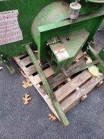
OP here again....Well it all worked great until it didn't....The lower flange mounted bearing detonated on me....Of course the chain flies off the gears....

I'm not sure why it blew....the Ransomes has an electric PTO clutch....maybe the shock of it going on was too much for the bearing....

I wish the PTO clutch was manual so I could ease it into gear....

Well I'm in the process of pulling it apart now....

What's my plan?....same bearing will last the 3 hours I got out of the other one.....

Is there a better/higher quality bearing I should try?

What ever help will be appreciated....

Mike
 

Attachments

  • IMG_6718[1].JPG
    IMG_6718[1].JPG
    190.1 KB · Views: 97
  • IMG_6719[1].JPG
    IMG_6719[1].JPG
    275.5 KB · Views: 103
  • IMG_6721[1].JPG
    IMG_6721[1].JPG
    293.6 KB · Views: 87
  • IMG_6723[1].JPG
    IMG_6723[1].JPG
    215.2 KB · Views: 96
  • IMG_6720[1].JPG
    IMG_6720[1].JPG
    262.1 KB · Views: 87
   / Need to change input/output shaft direction #32  
I'd say it is due to only one flange bearing face mounted per shaft.
I'd think you be OK if you were inside a 'box' with bearings at both ends of those shafts.
The side load on a single face mounted bearing must be tremendous especially with shock loads.
Just remove the mounting plate and duplicate it with 2 added bearings to support both ends of the shafts.
On the upper one you only need to simply face mount the bearing.
In effect U need to create a box.

As to auger settings, you want them to alternate otherwise the fan gets bigger gulps at every rotation vs a continuous more even flow.
Parallel will actually cause a surge at each rotation or a pulsation that actually would be detrimental to whatever weakest link in your design.

Oh, and I once did rig a front powered blower on my CUT but with its own separate engine.
So I'd suggest your next issue will be chain stretch but that you can monitor and replace B4 and damage occurs.
Just try to replace B4 the chain starts to skip as that would soon trash the sprockets.

Good luck, a 'fun project'.
 
Last edited:
   / Need to change input/output shaft direction
  • Thread Starter
#33  
Thanks Piloon....It's hard to see but I do have 2 of those flange mounted bearings on each shaft....I sandwiched them on either side of that steel plate I mounted everything on....Here's an earlier picture before the explosion.....

I think your right about the shock of that PTO being turned on....I'll put on the same bearings and I'll keep the rpms as low as I can go before engaging the PTO....I'll see what happens

Thanks, Mike
 

Attachments

  • IMG_6727[1].JPG
    IMG_6727[1].JPG
    242.8 KB · Views: 85
  • IMG_6724[1].JPG
    IMG_6724[1].JPG
    181.5 KB · Views: 83
   / Need to change input/output shaft direction #34  
OK, mounted like that, back to back still IMHO is much to much stress on that plate which I am guessing looks like a 5/16 or 3/8" plate.
Heck the shock load tore it apart. That's some forces!
 
   / Need to change input/output shaft direction #35  
It looks to me, from your pictures, like the bearing housing, not the bearing itself, failed. It also looks like the housing is aluminum and that the outer diameter of the bearing race is cylindrical, not spherical. If the preceding is all correct then it may be bearing mis-alignment has caused the problem. It could be that the inner and outer bearings were not exactly aligned with each other. And the aluminum housing eventually broke from the side load stress. Flange mount bearings are available that use bearings with spherical outer race diameters. That was clumsy. The outer bearing race is ground such that the outer diameter is a section of a sphere. This allows it to swivel in the housing to accommodate non-parallel mounting and other problems. Does the shaft that goes through the two bearings spin easily? If it doesn't then something is binding and it looks to me like the thin aluminum housing took the brunt of the stress. There could also be shock loads when the chain gets tight when power is first applied and lessening these shock loads could help. But if the bearing housing is already breaking then what if your snow blower suddenly tries to blow something hard. Is that going to once again break bearing housings? Boy, I sure made a lot of assumptions by looking at your pictures. I hope I didn't waste your time.
Eric
 
   / Need to change input/output shaft direction #36  
Just asking the question. With OP's 2 bearings basically back to back, as a system should we look at the bearings as one unit not as two separate bearing mounted on different plates like Piloon was suggesting in post 32? Maybe OP needs to separate the bearings further from another and use a better bearing housing material. Is 3 or 4 bolt flange bearing stronger than a two bolt flange of the same material? On my pto driver snowblower, I always idle the pto speed before engaging the pto. Can the OP do that with the electric clutch? Just some thoughts and questions. Jon
 
   / Need to change input/output shaft direction #37  
I agree with the observations above. Even though you have two bearings, they are really only acting as one, under tremendous loads (including side loads, harmonic loads from the chain, and alternating drive loads as the drive train is torque loaded). If the housing had not broken, the bearing would have failed in time. That drive chain can exert several tons for tension force on that driveshaft, and the leverage of that shaft in two very closely spaced bearings multiplies that by maybe ten. The bearings cannot withstand that. At the very least, the chain sprockets must be between two bearings. The distance from the bearing to the center of the U joint should not exceed the distance between the two bearings which span the sprocket.

I have made a very similar arrangement, when I converted my snowblower from front mount to three point, and it has worked very well. I removed the original gearbox ('cause it reduced, instead of the needed increase from PTO speed), and installed four bearings, and two sprockets. I made it extra robust, as it doubles the PTO speed to be the 1200RPM input that the blower requires, so added load from that too. What I built is this:

IMG_7132.JPG
 
Last edited:
   / Need to change input/output shaft direction
  • Thread Starter
#38  
The autopsy is complete...looks like you guys were right...shock load on the bearing cases was just too much...

Even the 2nd bearing housing behind the shattered one was split almost in half....

I found a picture of a blower that's for sale that has what might work....this looks like what you guys were describing....the shaft that takes the shock load from the PTO is separated by metal housing flange parts and front and back bearings in multiple spots on the shaft....

I want to get away from this chain and sprocket set-up....

Is there a gear reducer box I can purchase?....The blower worked great when it was running....

My shop manual says that the PTO rpm at full throttle is 3500....I'll need that rpm reduced down to 700 or a 5 to 1 reduction....PTO spins clockwise and I'll need out put of the gear box to also be clockwise.....

The gear box that came with the blower is clockwise in and counter clock out...no good....

Help me find the correct gear box....

Thanks, Mike
 

Attachments

  • IMG_6737[1].JPG
    IMG_6737[1].JPG
    243.2 KB · Views: 73
  • IMG_6738[1].JPG
    IMG_6738[1].JPG
    246.5 KB · Views: 74
  • IMG_6748[1].JPG
    IMG_6748[1].JPG
    252.5 KB · Views: 76
  • 261167762_6874918702533363_8388092896857687372_n.jpg
    261167762_6874918702533363_8388092896857687372_n.jpg
    703.2 KB · Views: 73
  • IMG_6747[1].JPG
    IMG_6747[1].JPG
    231.8 KB · Views: 79
  • IMG_6724[1].JPG
    IMG_6724[1].JPG
    181.5 KB · Views: 73
   / Need to change input/output shaft direction #39  
Put some good quality CAST IRON four bolt flange self centering bearings on instead of those two bolt pot metal housing items you tried first..

DAYTON sells all sort of products, not all of them are worth the trouble. Check out Bailey's or Hydraulic supply for ideas.

The Dodge catalog will provide load ratings.


I feel the attachment of your secondary plate is a bit fragile, Add a couple of studs top and bottom back to the blower housing. Your design is sound. Just fit it with bearings that are up to the task!

Shock really has little to do with the failure.
 
Last edited:
   / Need to change input/output shaft direction #40  
The blower fan should probably be turning more like 1000-1200RPM if the fan diameter is around 16", which is common for small ones. Only less than 1000 RPM if the fan is bigger than 20" diameter. Durst are a gearbox manufacturer, but what you're looking for is odd. The gearbox must have an idler inside so clockwise in is also clockwise out. My blower had one, I had to remove it, and go with the chain instead. The chain will be fine as long as the shaft is correctly supported with the bearings well apart, preferably spanning the chain sprockets. Coupling a gearbox will introduce its own challenges.
 
 
Top